The information in this Wiki Page applies to Surveyor 2.0 (S20) as found in Trainz Plus and TRS22 Platinum.
There is a companion Trainz Wiki Page  How to Use S20 Palettes that covers the all Palettes and Windows, both for Surveyor 2.0 and Driver, found in Trainz Plus and TRS22 Platinum. How to Use S20 Palettes that covers the all Palettes and Windows, both for Surveyor 2.0 and Driver, found in Trainz Plus and TRS22 Platinum. |
| |
|
|
|
|
 |
 |
|
|
| Surveyor 2.0 Mouse and Keyboard Aids and Shortcuts |
|
|
Operations |
| LClick |
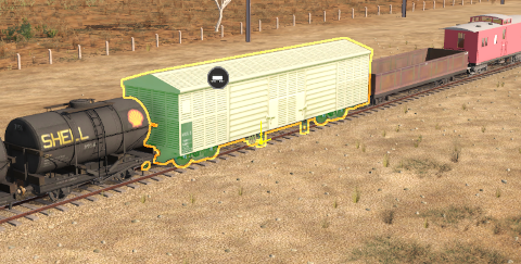
Left Click on an object to Select it |
| Shift LClick |
hold down the Shift key and Left Click on another object to add it to the Selection |
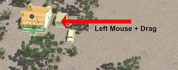
| LClick Drag |
Left Click and Drag to Move an object or a group of selected objects |
| RClick |
Right Click on the terrain to Move the Compass Rose and Focus to that location or to open a setting menu in a palette |
| DLClick |
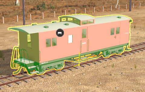
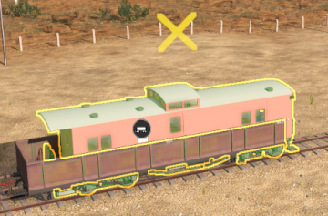
Double Left Click on an object to add it and all nearby identical objects into a single Selection
 |
when used on a consist all the wagons in the consist, regardless of type, will be selected |
|
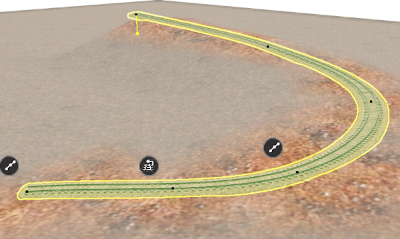
when used on a spline or track all the segments upto the next junction or last endpoint (in both directions) will be selected. This is a useful trick for finding track (or any spline) endpoints that have not been correctly joined together |
|
| Shift DLClick |
hold down the Shift key and Double Left Click on another object to add it and its nearby identical objects to those already in the Selection |
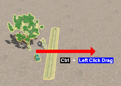
| Ctrl LClick Drag |
hold down the Ctrl key and Left Click and Drag to Clone an object or selected objects |
| Ctrl C |
press Ctrl + C to Copy selected objects (including the ground heights, ground textures and any TurfFX/Clutter Effect Layers) into a new Scrapbook |
| Ctrl D |
press Ctrl + D to Unselect a selected object (or ALL objects if multiple objects have been selected). Also removes the boundary lines from a Marquee Selection Area |
| Ctrl E |
press Ctrl + E to open the Route Editor (to edit the route name, description, thumbnail, scale, etc) |
| Ctrl F |
press Ctrl + F to open the Object Finder |
| Ctrl F1 |
press Ctrl + F1 to switch from Driver to Surveyor via the UDS interface |
| Ctrl F2 |
press Ctrl + F2 to switch from Surveyor to Driver via the UDS interface |
| Ctrl M |
press Ctrl + M to open the Mini Map |
| Ctrl R |
press Ctrl + R to open the Session Editor (to edit the session name, description and rules) |
| Ctrl S |
press Ctrl + S to Save the current route and/or session (which ever has been edited) |
| Ctrl V |
press Ctrl + V to Paste the current Scrapbook into the route at the cursor position (the Surveyor Compass Rose). The current settings in the Scrapbook Palette Filter will control which objects are pasted and how they are pasted |
| Ctrl X |
press Ctrl + X to Cut and remove selected objects from the route and place them into a new Scrapbook. The ground heights, ground textures, TurfFX/Clutter Effect Layers and any selected objects that are in locked layers will be copied into the Scrapbook, not cut |
| Ctrl Y |
press Ctrl + Y to Redo (reverse) the last Ctrl Z command |
| Ctrl Z |
press Ctrl + Z to Undo previous actions |
| Ctrl Space |
press Ctrl + Space to show/hide the User Interface. The Trainz Main Menu icons and all the docked palettes in the sidebars will be hidden while "free floating" palettes will still be visible and usable |
| Alt |
hold down the Alt key and hover the tool pointer over an object to Identify it |
| Alt LClick |
hold down the Alt key and Left Click on an object to Select it in the Assets Palette and to copy some data from the object to the Tool Options Palette |
| Delete |
press the Delete key to Delete a selected object or objects from the route |
|
|
Tools a LClick on an Icon will also select it |
| W |
selects the Brush Tool  |
 |
| E |
selects the Placement Tool  |
| R |
selects the Eyedropper Tool  |
| S |
selects the Free Move Tool  |
| D |
selects the Fine Adjustment Tool  |
| F |
selects the Marquee Tool  |
| T |
opens the Context Menu of a selected object |
| |
Object Context Icons:  |
|
|
 |
Further information on the topics mentioned in the above list can be found in Trainz Wiki Pages at:-
|
| The Surveyor Tools |
 |
 |
Assets and Objects
(based on the Surveyor 2.0 Overview document)
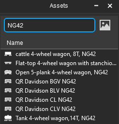
In this online documentation, the term Asset is used when discussing the items listed in Content Manager and the Assets Palette . When an asset is placed into the Trainz World then it will be referred to as an Object. |
|
|
| Navigation Icons used in this Document |
 |
at Chapter Headings to jump to the top/bottom of the document |
 |
at Chapter Headings to jump to the next or previous Chapter
e.g. 1. to 2. to 3., etc |
  |
within Chapters to jump to the next or previous Section
e.g. 3.1 to 3.2 to 3.3, etc |
 |
within Sections to return to the current Chapter Heading
e.g. 3.3 back to 3.0 |
  |
within Sections to jump to the next or previous Sub-section
e.g. 3.1.1 to 3.1.2 to 3.1.3, etc |
 Link Link |
Internal link to another section within this document |
| Link |
External link to another document |
|
|
| Colour Coded Labels used in this Document |
| Palette |
Name of a palette e.g. Assets Palette |
| Option |
Drop Down Menu option e.g. Copy |
| Key |
Keystroke or keystroke combination e.g. Shift or Ctrl + C |
| Control |
A control setting in the Tool Options Palette e.g. Radius |
| Mouse |
An action to be performed using the mouse e.g. Left Click and Drag |
|
|
Surveyor 2.0 vs Surveyor Classic
|
|
|
|
|
|
|
| Surveyor 2.0 |
| Surveyor 2.0 (or S20) is the new Surveyor interface provided to Trainz Plus and TRS22 Platinum as an alternative to Surveyor Classic which has existed since 2002. Surveyor Classic is still available as an option in Trainz Plus and TRS22 Platinum. |
| Whats New |
 |
a single set of common tools that can be applied to ALL types of objects |
|
the ability to select multiple objects of different types that can be manipulated as one with more freedom than was previously possible |
|
each object has its own Context Menu that applies specific actions depending on the type of object |
|
information and controls in dockable and moveable Palettes that can be hidden when not needed |
|
a new Scrapbook asset to store "scenes" that can be pasted anywhere in a route, between routes and shared through the DLS |
|
a new Marquee Tool that allows:-
|
multiple baseboards to be added, deleted and have their heights, ground texture and grid resolutions changed in a single operation |
|
objects, ground heights, ground textures and TurfFX/Clutter Effect Layers to be moved and copied |
|
|
HD Resolution in Trainz Plus |
|
Color Effect Layer in Trainz Plus routes that use HD Resolution |
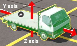
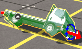
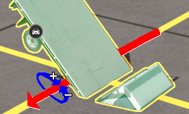
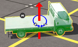
The following screen images help illustrate the change in philosophy that has occurred with the release of the Surveyor 2.0 user interface.
|
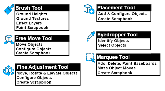
The Tools Palette is at the core of Surveyor 2.0 and takes the place of all the Tool Flyouts that have been the standard for Trainz Surveyor for many years. Some of the tools are new while others have been given a makeover and new abilities. |
 |
A Palette is a screen box containing tools, controls and/or information that can be hidden/revealed, moved around the screen, resized, docked and undocked with other palettes. There is a Trainz Wiki Page specifically covering the S20 Palettes at How to Use the Surveyor 2.0 Palettes |
|
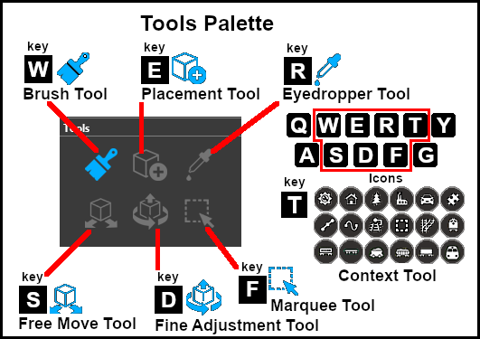
The Context Tool is attached as an icon to a selected or newly placed object. The icon design will vary according to the type of object.
|
|
|
Detailed information and instructions for using each of these tools can be found in the links below:- |
|
|
|
 |
Keyboard Shortcut: W |
|
|
The Brush Tool "paints" ground heights, ground textures, effect layers and scrapbook scenes into your Trainz World |
 |
Various function of this tool use the Scrapbook Palette Tool Options Palette Info Palette Filter Palette and the Assets Palette . If these palettes are not visible on the screen when required then refer to Notes: Palettes at the top of this document. |
|
The Brush Tool has two drop down menu lists.
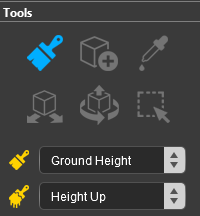 |
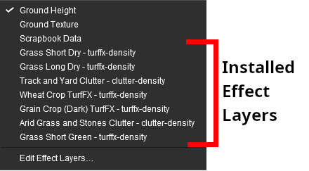
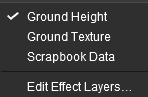
 Brush Targets The first drop down menu will set the "Brush Target" which is the type of brush. Left Click on the drop down box and on a Target to select it. The Brush Targets are:- Brush Targets The first drop down menu will set the "Brush Target" which is the type of brush. Left Click on the drop down box and on a Target to select it. The Brush Targets are:- |
 |
Ground Height |
|
Ground Texture |
|
Scrapbook Data |
|
<List of Effect Layers> |
|
Edit Effect Layers |
|
 |
If you have any Effect Layers then they will appear as Targets in this Drop Down Menu. Select an Effect Layer to use the brush to paint with that layer. See Effect Layers below for more details |
 Brush Actions The second drop down menu will set the "Brush Action" which is how the brush works. Its options will vary with the bush target selected (see the following sections) and for some targets no options will appear meaning that the selected brush target does not have any different actions Brush Actions The second drop down menu will set the "Brush Action" which is how the brush works. Its options will vary with the bush target selected (see the following sections) and for some targets no options will appear meaning that the selected brush target does not have any different actions |
|
|
|
The Brush Tool is used to "paint" the following data and object types into a route:- |
|
|
|
|
This Brush Target raises or lowers the Ground Surface Height by using a "painting" action |
|
All the Terrain Features in your Trainz World such as hills, valleys, railway cuttings and embankments, river and lake beds, are created using the Ground Height Brush |
|
|
This Brush Target uses the Tool Options Palette . If this palette is not visible on the screen then refer to Notes: Palettes at the top of this document.
|
|
| Brush Actions |
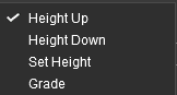
When the Ground Height Target is selected, the second drop down box will give a choice of several brush actions that control how the ground height is adjusted. |
|
| The actions are:- |
|
Height Up |
|
Height Down |
|
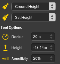
Set Height |
|
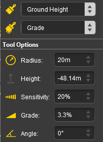
Grade |
|
 |
 |
The Tool Options Palette Sensitivity setting controls the rate or speed at which the height will be changed under the brush as you move it across the terrain.
100% = fastest: 1% = slowest |
|
|
|
| Ground Height Brush Actions: |
Height Up
Height Down |
raises/lowers the ground under the brush at a rate controlled by the Tool Options Palette Sensitivity setting |
| Set Height |
"plateaus" the ground under the brush to the Tool Options Palette Height setting at a rate controlled by the Sensitivity setting |
| Grade |
creates a smooth slope under the brush at the Tool Options Palette Grade and Angle settings at a rate controlled by the Sensitivity setting |
|
|
|
Ground heights are saved in the special Ground Height layer in the Layers Palette |
|
 |
This layer cannot be renamed, deleted, moved or merged with any other layer |
|
Most ground height edits are performed using the Brush Tool. Edits can also be performed using the Marquee Tool. Limited ground height edits under a selected object or objects can be performed using the Smooth Ground Under Selected option in the objects Context Icon. |
|
5m Resolution, 10m Resolution, HD Resolution
|
|
|
|
|
|
|
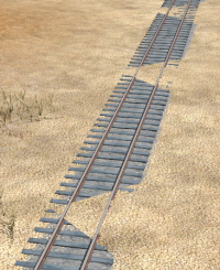
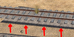
The choice of baseboard resolution affects the level of detail that it is possible to achieve in the ground terrain (for ditches, track beds, rail embankments and cuttings, etc) and the ground texture. The choice will also affect the physical size, in KB or MB, of the route when it is saved.
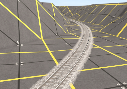
Rail cutting through 10m Resolution terrain |
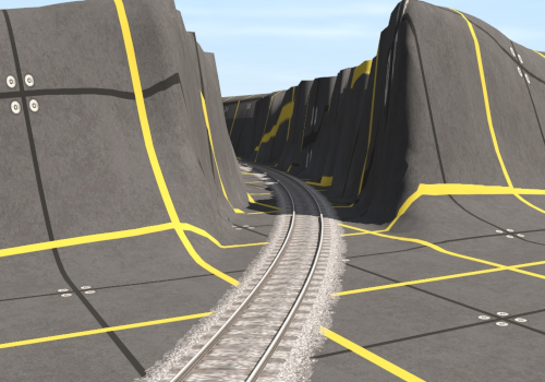
Rail cutting through HD Resolution terrain |
For more information on how your choice of resolution affects the ground height and ground textures, see Ground Height Brush Size and Grid Size, Ground Texture Brush Size and Grid Size and HD Resolution and Ground Textures below. |
| The choices are:- |
| 10m Resolution |
This has been the standard resolution since the earliest days. It gives the lowest level of detail and the smallest file sizes. A baseboard with a resolution of 10m will allow the unrestricted use of brushes with a radius down to 10m. Brushes of less than 10m can still be used but with reduced accuracy |
| 5m Resolution |
This was a later addition to the Trainz World. It gives about 4x as much detail as the 10m Resolution but with an increase in file sizes. A baseboard with a resolution of 5m will allow the unrestricted use of brushes with a radius down to 5m. Brushes of less than 5m can still be used but with reduced accuracy |
| You can have both 10m Resolution and 5m Resolution baseboards in the same route. Placing, for example, the 10m Resolution baseboards away from the tracks where a higher level of detail may not be needed, and the 5m Resolution baseboards under and close to the tracks where more detail may be needed |
| HD Resolution |
This is the latest addition to the Trainz World. It gives the highest level of detail, up to 6,400x greater than the 10m Resolution, but with a signficant increase in file sizes. A route set to HD Resolution will allow the unrestricted use of brushes with a radius down to 0.12m (12cm). Smaller brush sizes are not possible.
Important HD Notes:
|
HD Resolution is only available in Trainz Plus |
|
It is NOT RECOMMENDED that you mix HD Resolution baseboards with 10m or 5m Resolution baseboards in the same route. HD baseboards have unwanted visual effects where they meet 10m and 5m baseboards |
|
HD routes are restricted to using a maximum of 16 textures per baseboard , but each baseboard can have 16 different textures. This is a limit imposed by your hardware, not by Trainz. See HD Resolution and Ground Textures for more details and how to work around this limitation |
|
|
In Trainz Plus and TRS22PE the level of file compression used when saving .cdp files was significantly increased to reduce the size of the files. The size limit for a .cdp file is 1 GB but larger assets, such as routes, can be saved by using Content Manager to open the asset in Windows Explorer and saving the folder using commonly available file compression software such as 7Zip or WinRAR |
|
|
|
The resolution is set when a route is created and new baseboards are added but it can be changed at any time |
|
Identifying the Grid Resolution
|
| When you load a route into Surveyor there may be no obvious clues as to what the resolution of its baseboards actually are and routes can have a mixture of baseboards set to 10m Resolution and 5m Resolution.
|
 |
How Can You Identify the Resolution of a Baseboard or Route? |
| |
The only reliable way to check the resolution of a selected baseboard is to use the Ground Height Brush and set its radius to specific values to test the baseboard. The available resolutions are HD (in Trainz Plus only ), 10m and 5m. It is possible to mix both 10m and 5m baseboards in the same route so adjoining baseboards can have different resolutions.
|
Quick HD Check: In Trainz Plus if you are near an edge baseboard then look over the edge. If you see a vertical wall dropping down then the route is using 5m and/or 10m Resolution. If no vertical wall is seen then it is using HD Resolution |
|
|
Setting and Converting Grid Resolutions
|
Grid Options
| In TRS22PE:- |
|
10m Resolution - this is the default resolution when a new route is created and for each new baseboard added but you will have the option of changing the resolution when adding baseboards |
|
5m Resolution - you can set 5m as the resolution for each new baseboard when it is added. You can have a mixture of 5m and 10m Grid baseboards in the same route |
|
HD Resolution routes can be loaded into TRS22PE but the HD terrain will not appear at the same level of "sharpness" as it would in Trainz Plus - it will be "smoothed" to a lower resolution. The ground heights in HD routes cannot be edited in TRS22PE unless the baseboards are converted to 5m Resolution or 10m Resolution |
|
| |
| In Trainz Plus:- |
|
HD Resolution (0.125m or 12.5cm) - this is the default resolution when a new route is created and for each new baseboard added but you will have the option of changing the resolution when adding baseboards. If you are using HD Resolution then it is recommended that ALL the baseboards should use HD Resolution |
|
5m Resolution - you can set 5m as the resolution for each new baseboard when it is added. You can have a mixture of 5m and 10m Grid baseboards in the same route |
|
10m Resolution - you can set 10m as the resolution for each new baseboard when it is added. You can have a mixture of 5m and 10m Grid baseboards in the same route |
|
|
Grid Conversions
| In TRS22PE:- |
| The Marquee Tool is used to:- |
|
add individual and multiple baseboards. You can select their resolution from 5m Resolution and 10m Resolution and you can use both resolutions in the same route |
|
convert individual and multiple baseboards between 5m Resolution and 10m Resolution and from HD Resolution to either 5m Resolution or 10m Resolution |
| |
See Managing Baseboards for more details on adding and converting baseboards |
| In Trainz Plus:- |
| The Marquee Tool is used to:- |
|
add individual and multiple baseboards. You can select their resolution from HD Resolution, 5m Resolution and 10m Resolution. It is NOT RECOMMENDED that you mix HD Resolution baseboards with 10m or 5m Resolution baseboards in the same route |
|
convert individual and multiple baseboards between HD Resolution, 5m Resolution and 10m Resolution. It is NOT RECOMMENDED that you mix HD Resolution baseboards with 10m or 5m Resolution baseboards in the same route |
| |
See Managing Baseboards for more details on adding and converting baseboards |
The  Surveyor Tools Menu has an option that will convert an entire route from 5m and/or 10m Resolution to HD Resolution in a single step. See Upgrading a Route to HD Surveyor Tools Menu has an option that will convert an entire route from 5m and/or 10m Resolution to HD Resolution in a single step. See Upgrading a Route to HD |
|
|
|
Notes:
|
|
HD Resolution routes are restricted to using just 16 different ground textures per baseboard, but each baseboard can have 16 completely different ground textures.
See HD Resolution and Ground Textures below for more information |
|
With each increase in Resolution (from 10m to 5m to HD) there will be an increase in the route file size |
|
Converting to a higher Resolution (e.g. from 10m to 5m or to HD) will not automatically increase the surface details that will be shown. You will have to do that work yourself |
|
Converting to or from HD Resolution will "smooth" the surface details so a sharp ridge line, for example, will become a smoother ridge line. You may need to manually edit the ground terrain |
|
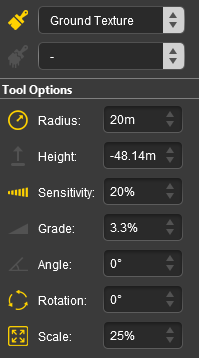
Ground Height Brush Tool Options
|
|
|
|
|
|
|
|
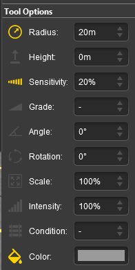
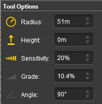
Notes: Tool Options Palette Controls
|
|
The active ground height brush options for each action are shown in the Tool Options Palette with a Gold coloured icon next to their names. Those options that have their icon greyed out will be ignored by the selected action, but they can still be edited. |
|
Most of the data entry boxes in the Tool Options Palette have a Popup Menu (Right Click inside the box) that can be used to collect and distribute data - see the Trainz Wiki Page How to Use the Surveyor 2.0 Palettes for more details. |
|
Height Up/Height Down
 |
Set Height
 |
Grade
 |
|
On the right of each data entry box is a pair of Up/Down arrow controls. Left Click and Drag up or down on these to adjust the value in smaller increments |
|
|
|
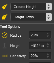
| Radius |
the brush radius (metres) |
| Range: |
for 5m Resolution and 10m Resolution see Notes: below
0.12m and above for HD Resolution (in Trainz Plus only) |
|
| Height |
the brush height (metres) |
|
|
| Sensitivity |
the rate at which the Height changes under the brush |
| Range: |
1% (very slowly) to 100% (very quickly) |
|
| Grade |
slope gradient - see Notes: below |
| Range: |
0% = flat ("Plateau" in Classic) to |
| |
±100% = steep (but not vertical) |
|
| Angle |
grade direction - see Notes: below |
| Range: |
0° (North) to ±359°
a negative value reverses the grade direction |
|
|
|
|
Notes:
|
|
Unlike Surveyor Classic, there is no upper limit to the brush Radius . Brushes of hundreds of metres (even kilometres) in size are possible. However, the performance will decrease as the brush radius increases. If you are using the brush to set an entire baseboard, or many baseboards, to a specific height then the Marquee Tool might be a better choice. |
|
There is a lower limit to the brush Radius that is dictated by the baseboard resolution (10m Resolution, 5m Resolution or HD Resolution). For the 5m Resolution and the 10m Resolution baseboards it is possible to have brushes smaller than the resolution but they will have restrictions imposed. These restrictions will increase as the brush becomes smaller. For HD Resolution the minimum radius is 0.12m. Note: HD resolution is only available in Trainz Plus .
See Ground Height Brush Size and Grid Resolution for the details. |
|
The Grade is defined as vertical rise divided by horizontal distance converted to a percentage figure. So a grade of 100% (the maximum allowed) would mean a slope formed by the height and distance both being the same value (e.g. a height increase of 50m over a distance of 50m). A vertical slope (a cliff) would have an infinite grade (cliff height divided by 0) which is currently impossible in Surveyor. The Grade setting is only active when the Grade Brush Action has been selected. It has no effect on the other Ground Height options. |
|
The Angle controls the compass direction when creating a grade in the ground surface - 0° = North, 180³ = South
Angles greater than 360° can be entered but will give the same result as the angle minus 360°. For example: 450° is exactly the same angle as 90° (450°-360°=90°) |
|
Identifying the Ground Height
|
|
|
|
|
|
|
|
You can copy the current Ground Height of any spot in the route into the Tool Options Palette Height setting. Once it has been copied the height can be applied to the Ground Height Brush or to any object in the route. |
|
|
To copy the Ground Height into the Tool Options Palette Height setting choose one of the following:-
Options: |
 |
Using the Eyedropper option found in all the tools |
| |
Steps:
 |
move the mouse pointer to the spot on the terrain |
 |
hold down the Alt key and Left Click |
|
This option is a good choice when there are no scenery objects (e.g. vegetation, splines, buildings, etc) over the ground being sampled by the eyedropper.
| Warning: This will switch the Brush Tool from Ground Height to Ground Texture for painting with the texture or grid pattern at the location clicked |
|
|
|
|
OR |
 |
Using the Compass and the Tool Options Palette Height setting |
| |
Steps:
|
Right Click at the spot on the terrain to move the Compass |
|
Right Click inside the Height setting box |
 |
Left Click on the menu option
Get Height at Compass |
|
| This option is recommended when there are scenery objects (e.g. vegetation, splines, buildings, etc) between the ground and the eyedropper. In these cases the object name shown in the eyedropper Tooltip is NOT the name of a ground texture or a grid pattern. |
|
|
|
OR |
 |
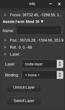
Using the Compass and the Info Palette |
| |
Steps:
|
Right Click at the spot on the terrain to move the Compass |
|
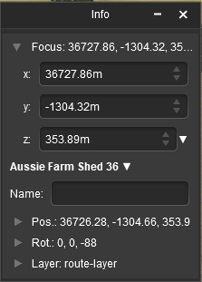
Open the Info Palette Focus controls |
|
Left Click the z: control down arrowhead icon |
 |
select the menu option
Use Height for Brush |
|
| This option involves more steps but is also recommended when there are scenery objects (e.g. vegetation, splines, buildings, etc) between the ground and the eyedropper. In these cases the object name shown in the eyedropper Tooltip is NOT the name of a ground texture or a grid pattern. |
|
|
|
"Painting" the Ground Height
|
|
|
|
|
|
|
|
The ground surface is "sculptured" up, down or to a set height by using a "painting action" with the Brush Tool |
| Steps: To set the Ground Surface Height:- |
|
You can jump directly to Step 3 by selecting the Ground Height layer in the Layers Palette |
|
|
In the Tools Palette Left Click on the Brush Tool or press the W key |
|
select the Ground Height target from the brush top drop down menu |
|
select the ( Height Up , Height Down , etc) action from the brush second drop down menu |
|
In the Tool Options Palette set any of the brush controls - Radius , Height , Grade , Angle , Sensitivity |
 |
Left Click and Drag on the terrain to change the terrain height |
|
|
Surveyor Classic has a Plateau Tool which allowed you to create a flat surface on the ground. The same task can be performed in Surveyor 2.0 by selecting the Set Height brush action and setting the Tool Options Palette Height control to the required value |
|
|
You can use the Marquee Tool to set a large area, an entire baseboard or several baseboards to a specific height. See Managing Baseboards for more details |
|
|
|
|
Notes:
|
|
The rate or speed at which the ground height changes under the brush is controlled by the Tool Options Palette Sensitivity setting
|
 |
Sensitivity Settings:
 |
1% for the smallest possible change with each sweep of the brush |
|
100% for the largest possible change with each sweep of the brush |
| Values between these two limits will give intermediate changes with each sweep of the brush over the same area |
|
|
|
|
Unlike Surveyor Classic, there is no upper limit to the brush Radius . Brushes of hundreds of metres (even kilometres) in size are possible. However, the performance will decrease as the brush radius increases. If you are using the brush to set the terrain of an entire baseboard, or many baseboards, to a set height then the Marquee Tool may be a better choice. |
|
There is a lower limit to the brush Radius that is dictated by the baseboard resolution (10m Resolution, 5m Resolution or HD Resolution). For 5m and 10m Resolutions brushes smaller than the set resolution are possible but will have restrictions that will increase as the brush becomes smaller. For HD Resolution the minimum radius is 0.12m. Note: HD resolution is only available in Trainz Plus .
See Ground Height Brush Size and Grid Resolution for the details. |
|
|
|
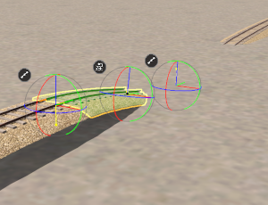
Most objects have a height value that can be set and altered using the objects Context Menu or through the Placement, Free Move and Fine Adjustment tools (see the sections below dealing with each of these tools for more details). |
|
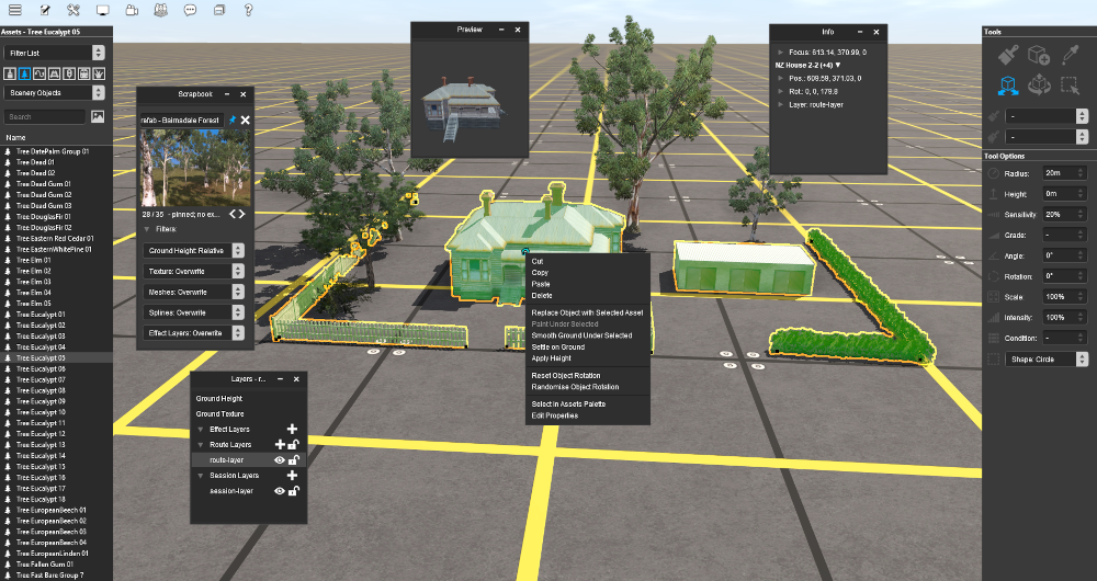
Object Context Menu Ground Height Options |
|
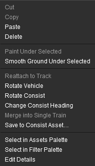
Once an object has been placed you can open its Context Menu ( Left Click on its icon or press the T key) to access a range of options and functions. The following Ground Height specific options will appear, along with other more general options, in the objects Context Menu.
|
| Smooth Ground Under Selected |
smooths the height of the ground under the selected object to match the set height of the object. The size of the area affected will depend on which has the greater value: the width of the object OR the Tool Options Palette Radius setting. If multiple objects at different heights have been selected then the ground height will be set to match, as far as possible, the heights of each object |
|
| Settle on Ground |
sets the height of the selected objects to match the height of the ground beneath them ("drops them back to earth") |
|
| Apply Height |
sets the height of the selected object to the value in the Tool Options Palette Height setting. Where multiple objects have been selected the context object, the one with the Context Icon, will have its height set to the Height value and the other selected objects will have their heights adjusted up or down by the same amount |
|
|
Ground Height Brush Size and Grid Resolution
|
|
|
|
|
|
|
|
The minimum allowed brush size is dictated by the set baseboard resolution |
|
Brushes that are smaller than the set resolution are possible but they will have restrictions on where they can be used |
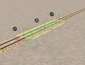
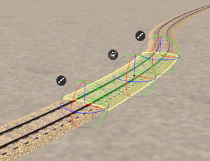
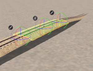
Ground Heights in 5m/10m Resolutions
|
| Ground height brushes can be smaller than the set 5m or 10m baseboard resolution. For example: you can alter the ground height with a brush size of 2.5m on a 10m Resolution baseboard but there will be restrictions on where you can use a bush that small. |
|
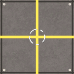
When the brush size is from 50% to under 100% of the Resolution (e.g. from 2.5m to 4.9m in a 5m Resolution baseboard or from 5m to 9.9m in a 10m Resolution baseboard) then it will work best when used on the grid lines - yellow lines for the 10m Resolution, and both grey and yellow lines for the 5m Resolution. Between the grid lines its effect will be reduced. |
|
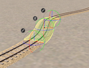
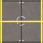
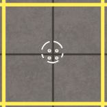
When the brush size is less than 50% of the Grid Resolution (e.g. <2.5m for the 5m Resolution or <5.0m for the 10m Resolution) then it will be restricted to the grid line intersections - yellow for the 10m Resolution, and both yellow and grey for the 5m Resolution as shown below. |
 |
 |
 |
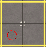 |
The RED brush circle in the last panel shown on the left indicates that the brush size is too small to work in that part of the grid square |
| Resolution: 5m Resolution - Brush Size: 1m |
|
|
Ground Heights in HD Resolution
|
|
You cannot have a brush size smaller than 0.12m (12cm) |
|
The brush is not restricted to grid lines or intersections and can alter the ground height anywhere within each grid square |
| The Surveyor Route Editor will allow you to switch between two minimum brush sizes when working with HD Resolution routes. |
| This option, available in Trainz Plus only, allows you to set the brush size to work in the default HD (High Definition) or at a lower SD (Standard Definition) which is easier to work with over larger areas.
|
Terrain Forming Tips
|
|
|
|
|
|
|
|
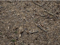
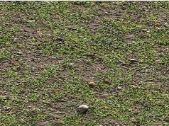
This Brush Target paints the currently selected Ground Texture (from the Assets Palette ) on the ground |
|
All the Terrain Textures in your Trainz World are painted onto the terrain using the Ground Texture Brush. These textures create the appearance of different soils, rocks, grasses and artificial surfaces (concrete, asphalt, gravel, etc) |
|
|
This Brush Target uses the Tool Options Palette , Filter Palette and Assets Palette . If these palettes are not visible on the screen then refer to Notes: Palettes at the top of this document.
|
|
| Brush Actions |
When the Ground Texture Target is selected, the second drop down box will be disabled - there are no brush texture actions. |
|
|
Ground textures are saved in the special Ground Texture layer in the Layers Palette |
|
|
This layer cannot be renamed, deleted, moved or merged with any other layer |
|
Ground texture edits are mostly performed using the Brush Tool. They can also be performed using the Marquee Tool. Limited ground texture edits under a selected object or objects can be performed using the Paint Under Selected option in the objects Context Icon. |
|
Ground Texture Brush Tool Options
|
|
|
|
|
|
|
|
Notes: Tool Options Palette Controls
|
|
The active texture brush options are shown in the Tool Options Palette with a Gold coloured icon next to their names. Those options that have their icon greyed out will be ignored, but they can still be edited. |
|
Most of the data entry boxes in the Tool Options Palette have a Popup Menu (Right Click inside the box) that can be used to collect and distribute data - see the Trainz Wiki Page How to Use the Surveyor 2.0 Palettes for more details. |
|
|
Notes:
|
|
Unlike Surveyor Classic, there is no upper limit to the brush Radius . Brushes of hundreds of metres (even kilometres) in size are possible. However, the performance will decrease as the brush radius increases. If you are using the brush to paint an entire baseboard, or many baseboards, then the Marquee Tool will be quicker but it will not give you the options of changing the scale and rotation while painting the texture. |
|
There is a lower limit to the brush Radius that is dictated by the baseboard resolution (10m, 5m or HD). For the 5m and the 10m Resolutions it is possible to have brushes smaller than the set Resolution but they will have restrictions imposed. These restrictions will increase as the brush becomes smaller. For HD Resolution the minimum radius is 0.12m. Note: HD resolution is only available in Trainz Plus .
See Ground Texture Brush Size and Grid Resolution for the details. |
|
The Rotation controls the starting compass angle (0° = North, 180° = South) for the texture when painting and is often used to avoid pattern repetition. As in Surveyor Classic, holding down the [ or ] keys while painting will continuously change the rotation angle in increments of ±10° |
|
|
Identifying and Selecting a Ground Texture
|
|
|
|
|
|
|
If you have a ground texture in your route that you want to identify or select again.
| Steps: To Identify an existing Ground Texture used in the Route:- |
|
Move the mouse pointer onto the texture to be identified and hold down the Alt key. The textures name name will appear in the pointers ToolTip |
| Steps: To Select an existing Ground Texture used in the Route:- |
|
While holding down the Alt key Left Click on the texture |
The texture will be selected in the Assets Palette , the Brush Tool and its Ground Texture target will also be activated so you can immediately start painting with that texture using the current Tool Options Palette settings. This will also copy the Ground Height at the selected point into the Tool Options Palette Height setting but this value is ignored when painting with a texture. |
|
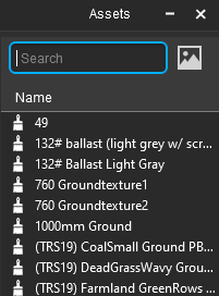
If a ground texture is not in your route or it is not visible in your Surveyor view, then it can be selected from the Assets Palette .
| Steps: To select a new Texture:- |
|
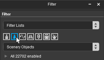
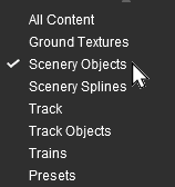
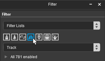
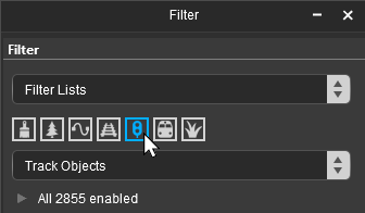
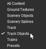
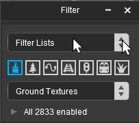
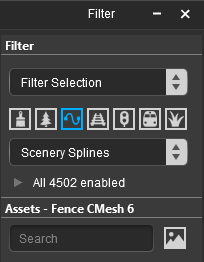
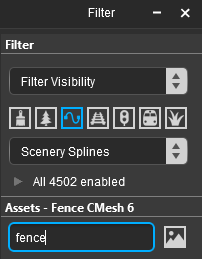
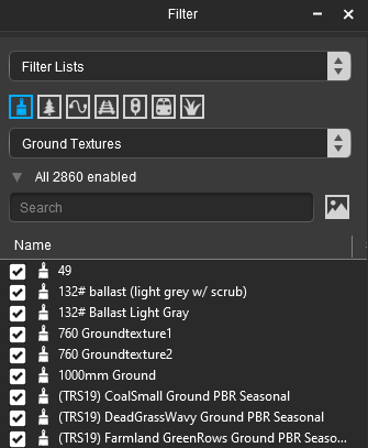
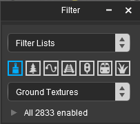
In the Filter Palette if the Ground Textures  icon, the first icon in the list, is not selected (shown in blue) then Left Click on the icon or select Ground Textures from the Content Drop Down Menu. icon, the first icon in the list, is not selected (shown in blue) then Left Click on the icon or select Ground Textures from the Content Drop Down Menu. |
| |
|
You can create a Picklist of your favourite or most used textures which will always be available every time you load Surveyor. See the Trainz Wiki Page How to Create a Picklist for the details |
|
|
 |
|
|
|
|
Painting a Ground Texture
|
|
|
|
|
|
|
| Steps: To Paint with a Ground Texture:- |
|
If the Assets Palette is already showing the list of ground textures then you can jump directly to Step 5 or Step 4
Otherwise you can still jump directly to Step 4 or Step 5 by selecting the Ground Texture layer in the Layers Palette |
|
|
In the Tools Palette Left Click on the Brush Tool or press the W key |
|
select the Ground Texture from the brush Target Drop Down Menu |
|
In the Filter Palette select the Ground Texture list by a Left Click on the icon (the first icon in the row) |
|
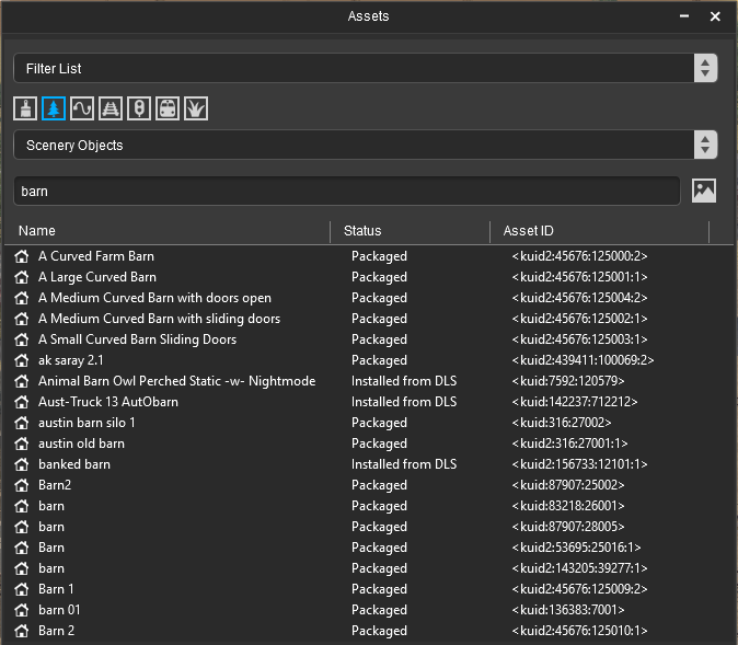
In the Assets Palette you have the option of narrowing the search by entering the name or a partial name of the texture in the Search box |
|
In the Assets Palette select the required Ground Texture from the filtered list |
 |
In the Tool Options Palette set any brush controls - Radius , Sensitivity , Rotation , Scale |
 |
Left Click and Drag on the terrain to start painting |
|
|
|
You can use the Marquee Tool to paint a large area, an entire baseboard or several baseboards with a selected ground texture. See Managing Baseboards for more details |
|
You can set a default Ground Texture that will automatically cover every new baseboard added. See Default Baseboard Ground Texture below for more details |
|
|
|
|
|
Notes:
|
|
The intensity at which the ground texture is painted is controlled by the Tool Options Palette Sensitivity setting. This allows you to paint over an existing texture (including the Grid pattern) in a way that will let most, some or none of the original texture show through
|
|
Sensitivity Settings:
|
1% to make the new texture almost transparent. The level of transparency will decrease with each new brush sweep over the same area |
|
50% to make the new texture 50% or semi-transparent |
|
100% to make the new texture completely hide the original texture with a single sweep of the brush |
| Values between these two limits will give intermediate changes with each sweep of the brush over the same area |
|
|
|
|
Unlike Surveyor Classic, there is no upper limit to the brush Radius . Brushes of hundreds of metres (even kilometres) in size are possible. However, the performance will decrease as the brush radius increases. If you are using the brush to paint an entire baseboard, or many baseboards, then the Marquee Tool will be quicker but it will not give you options for changing the brush properties when painting. |
|
There is a lower limit to the brush Radius that is dictated by the baseboard resolution (10m, 5m or HD). For the 5m and the 10m Resolutions it is possible to have brushes smaller than the set Resolution but they will have restrictions imposed. These restrictions will increase as the brush becomes smaller. For HD Resolution the minimum radius is 0.12m. Note: HD resolution is only available in Trainz Plus .
See Ground Texture Brush Size and Grid Resolution for the details. |
|
|
|
Most objects can have a Ground Texture automatically painted beneath them. |
|
Object Context Menu Ground Texture Option |
|
Once an object has been placed you can open its Context Menu ( Left Click on its icon or press the T key) to access a range of options and functions. The following Ground Texture specific options will appear, along with other more general options, in the objects Context Menu.
|
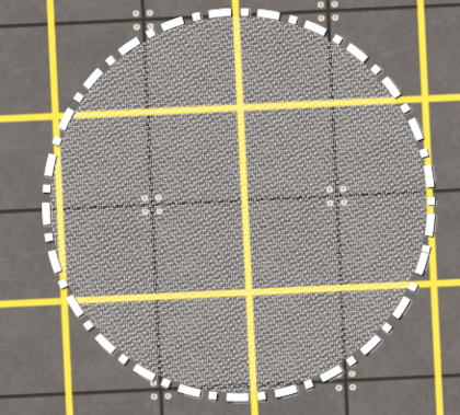
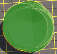
| Paint Under Selected |
the texture selected in the Assets Palette will be painted under the selected objects. The Tool Options Palette brush settings ( Radius and Sensitivity ) will control how the texture is applied. If no ground texture has been selected in the Assets Palette then this option will be greyed out. This option is frequently used to paint a texture under selected track (or other) splines.
|
|
Objects have a minimum brush size that represents the smallest area that can be painted beneath them using the Paint Under Selected option. This minimum area will vary in size between objects but it will be rectangular even for circular objects. If the Tool Options Palette brush Radius is set to a smaller size then the brush Radius will be ignored and the objects minimum brush size will be used instead. |
|
|
|
Ground Texture Brush Size and Grid Resolution
|
|
|
|
|
|
|
|
The minimum allowed brush size is dictated by the set baseboard resolution |
|
Brushes that are smaller than the set resolution are possible but they will have restrictions on where they can be used |
Ground Textures in 5m/10m Resolutions
|
| Ground texture brushes can be smaller than the set 5m Resolution or 10m Resolution baseboard size. For example: you can paint a ground texture with a brush size of 2.5m on a 10m Resolution baseboard but there will be restrictions on where you can use a bush that small. |
|
When the brush size is from 50% to under 100% of the Grid Resolution (e.g. from 2.5m to 4.9m in a 5m Resolution or from 5m to 9.9m in a 10m Resolution) then it will work best when used on the grid lines - yellow lines for the 10m Resolution, and both grey and yellow lines for the 5m Resolution. Between the grid lines its effect will be reduced. |
|
When the brush size is less than 50% of the Grid Resolution (e.g. <2.5m for the 5m Resolution or <5.0m for the 10m Resolution) then it will be restricted to the grid line intersections - yellow for the 10m Resolution, and both yellow and grey for the 5m Resolution as shown below. |
|
|
|
|
The RED brush circle in the last panel shown on the left indicates that the brush size is too small to work in that part of the grid square |
| Resolution: 5m Resolution - Brush Size: 1m |
|
|
Ground Textures in HD Resolution
|
|
You cannot have a brush size smaller than 0.12m (12cm) |
|
The brush is not restricted to grid lines or intersections and can paint a ground texture anywhere within each grid square |
|
You are restricted to using a maximum of 16 ground textures per baseboard (but each baseboard can have up to 16 different textures) |
| The Surveyor Route Editor will allow you to switch between two minimum brush sizes when working with HD Resolution routes. |
| This option, available in Trainz Plus only, allows you to set the brush size to work in the default HD (High Definition) or at a lower SD (Standard Definition) which is easier to work with over larger areas.
|
Texture Painting Tips
|
|
|
|
|
|
|
Default Baseboard Ground Texture
|
|
|
|
|
|
|
| When a new route is created or a new baseboard is added it will be covered with the ground texture for the selected Region or the default texture if no region has been set. This can be changed to a different texture (including to the standard TRS19/TRS22 grid pattern). |
 |
| Steps: To disable the current default ground texture (easiest method):- |
|
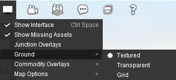
open the  Surveyor Display Menu Surveyor Display Menu |
|
select the Ground option |
|
select the Grid sub-option. This will use the current grid texture. |
|
|
| A more complex solution is to edit an existing Region or create one of your own to add your preferred ground texture (such as the standard TRS19/22 grid pattern) to each new route you create and every new baseboard that you add. |
|
Notes:
| The Baseboard Ground Texture, chosen from the Surveyor Display Menu or by specifying a Region, will become the default for every new route you create and every new baseboard you add, until you change it to something else. |
|
|
Information on creating and editing Region assets can be found on the Trainz Wiki Page at:-
|
|
|
|
HD Resolution and Ground Textures
|
|
|
|
|
|
|
|
HD Resolution is only available as an option in Trainz Plus |
|
The HD option provides a surface resolution in Trainz Plus of 0.125m (12.5cm) from the standard 5m or 10m resolutions. This gives you far more realistic terrain for cuttings, embankments, ditches, drains, the track bed, etc.
However, there is a price that has to be paid for using this feature. You will be limited to a maximum of 16 different ground textures PER BASEBOARD but each baseboard can have 16 completely different ground textures.
|
Notes:
This is a limitation imposed by your computer hardware and not one "plucked out of the air" by N3V to make life more difficult for route creators. Other sims/games that use High Definition (HD), or its equivalent, have the same or an even more restrictive limit (e.g. 8 textures per baseboard equivalent) |
|
|
|
What happens if you exceed the limit of 16 textures in a baseboard? |
|
|
If you have upgraded a route from 5m Resolution or 10m Resolution to HD Resolution (see Upgrading a Route to HD) then Trainz Plus will replace any textures in any baseboards that are over the limit with textures already used in those baseboards. The upgrade process will give you the x and y co-ordinates of all the altered baseboards so you can check for any visible changes |
|
If you are adding ground textures to a HD route and paint a new texture onto a baseboard that already has 16 ground textures, then the new texture will be replaced by one that is already present in that baseboard |
|
|
There is a simple way to get around the 16 textures per baseboard limit - add a Color Effect Layer (in Trainz Plus and HD routes only).
This layer allows different coloured tints to be painted over individual areas of the existing ground textures to alter their appearence and increase the range of colours in a baseboard.
The Color Effect Layer only works in routes that use the HD resolution. Details can be found in the Effect Layers section below. |
|
Using PBR Textures
|
|
|
|
|
|
|
|
PBR textures provide 3D effects such as a roughness or uneveness to surfaces |
|
When used as ground textures PBR can add a 3D effect |
| Painting with a PBR Texture is no different from painting with any ground texture. |
| Steps: To Use PBR Ground Textures in a Layout:- |
|
In the Filter Palette select the icon or Ground Textures option from the drop down list |
|
In the Assets Palette type PBR in the Search box |
|
Select a PBR texture from the filtered list - to see the actual textures Left Click on the Thumbnail View  icon. icon.
Selecting a texture will automatically select the Brush Tool and set its target to Ground Texture |
|
Optional: In the Tool Options Palette set any required brush controls - Radius , Sensitivity , Rotation , Scale |
|
Left Click and Drag on the terrain to start painting the texture
|
You can use the [ and ] texture rotation keys while painting with a PBR texture to break up any pattern repetitions but this can cause a "blurring" of the texture. A better technique is to periodically tap one of these keys as you paint with the texture instead of holding them down continuously. There will be a small penalty in that each texture rotation will load in a new copy of the PBR texture but personal experience suggests that even when PBR textures are used as the only textures throughout a large route the penalty is about a 5% increase in file size |
|
|
PBR Textures do have a few downsides compared to non-PBR textures. Specifically:-
|
They do not mix well with non-PBR textures and this can include a PBR texture used under track that has a non-PBR ballast. This can cause "issues" where the two different types of textures meet. There are techniques that can be used to eliminate these "PBR meets non-PBR" issues and most, if not all, Procedural Track assets now use PBR textured ballast |
|
Sudden (steep) changes in the ground height under a PBR texture can cause an "animation effect" under the texture that has been likened to "wobbling jelly" or moving "jellyfish guts". There are techniques that can be used to hide this effect |
These issues are not unique to Trainz and can be found in all games/sims that use PBR ground textures. Solutions and "work-arounds" are listed below.
|
Fix PBR Texture Conflicts
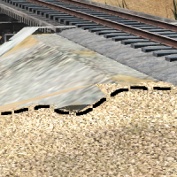
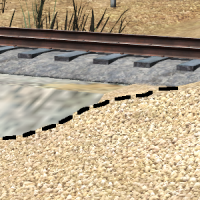
| Texture conflicts are at their most obvious where the PBR texture crosses a spline, such as a road or track. Triangle shapes and "shadow gaps" are formed where the overlap occurs, as shown in the images on the right. |
Triangle Textures
Shadow Gaps |
| Treatment |
|
|
Fix PBR Height Effects
PBR Textures have problems dealing with sudden changes in the height of the ground beneath them. This problem appears as an "animation effect" where the texture on the slope appears to move up or down as you change your point of view around the affected area. The effect is difficult to show using still images but the dotted line in the images on the right mark the texture upper surface lines in two different views of the same scene, an embankment leading to a rail bridge. As the camera view shifts the texture appears to change its height
|
  |
| Treatment |
| The recommended method is to use foliage to cover the area. The quantity and types of foliage will vary |
 |
|
|
This Brush Target paints the currently selected Scrapbook (from the Scrapbook Palette ) onto the ground |
|
The Scrapbook is a Surveyor 2.0 Clipboard that can hold multiple objects of different types. Like your operating system clipboard you can Cut or Copy selected objects into a new scrapbook and then Paste them anywhere in your route. The Scrapbook has additional features:- |
|
|
you can have multiple scrapbooks, that can be permanent or temporary, ready for use whenever Surveyor is started |
|
permanent scrapbooks can be saved as .cdp files by Content Manager and uploaded to the DLS for others to use |
|
you can Paint a scrapbook into a scene, using the Brush Tool, with a range of control options and Brush Actions |
|
you can control which types of objects in a scrapbook are painted or pasted and how they are painted/pasted. You can alter these controls to suit different situations |
|
|
This Brush Target uses both the Tool Options Palette and the Scrapbook Palette . If these palettes are not visible on the screen then refer to Notes: Palettes at the top of this document. |
|
Creating a Scrapbook
|
|
|
|
|
|
|
A new scrapbook is created by one of two methods:-
Options:
|
use the Marquee Tool to select an area of the route containing objects. You can use the filters in the Filter Palette and Assets Palette to restrict the objects that will be selected for the scrapbook OR |
|
use the Free Move Tool or the Fine Adjustment Tool to select a group of individual objects for the scrapbook. You can use the filters in the Filter Palette and Assets Palette to restrict the objects that will be selected for the scrapbook |
|
|
Steps: Copy or Move the Selected Objects into the Scrapbook:-
|
use either Option or Option above to select the objects to be included in the scrapbook |
|
if you intend to keep this scrapbook (make it permanent) then position your camera (screen point of view) to give the best view of the selected objects. The screen view will become the thumbnail when the scrapbook is created in Step 3 below |
|
then either:-
|
Left Click on the displayed Context Menu icon (or press the T key) and select either the Copy or Cut option OR |
|
press either Ctrl + C (Copy) or Ctrl + X (Cut) |
|
In both cases using the Ctrl + X or Cut options will remove the selected objects from your Trainz World if they are NOT in locked layers |
|
|
More detailed instructions on creating Scrapbooks can be found in the Marquee Tool section of this document
|
Scrapbooks will normally expire (self delete) after 5 days. Instructions on how to make a scrapbook permanent can be found at The Scrapbook Palette below |
|
|
|
|
|
|
Notes:
|
| Scrapbooks, when created, will contain:- |
|
Ground Heights |
|
Ground Textures |
|
TurfFX/Clutter Effect Layers - if present |
|
Selected Objects - scenery items, splines, track, signals, etc |
|
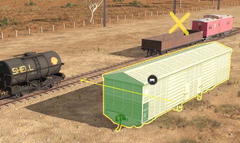
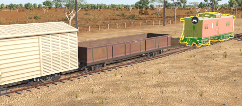
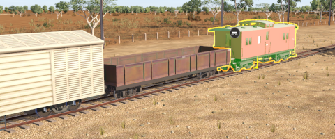
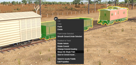
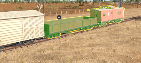
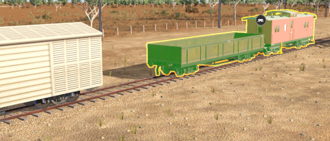
But NOT Rolling Stock (Trains) . Rolling Stock consists can be saved for later use as new Consist Assets. See Rolling Stock Object Context Menu for the details. |
| The ground heights, ground textures and TurfFX/Clutter Effect Layers in the Marquee Selection Area (method above) or under the selected objects (method ) will always be added to the scrapbook. You can use the filters in the Filter Palette and Assets Palette to control which other objects will also be added |
|
|
Pasting a Scrapbook
|
|
|
|
|
|
|
To paste a scrapbook into your Trainz World:-
| Steps: To Paste a Scrapbook:- |
|
Move the Compass Rose to the position where the scrapbook will be placed
|
You can immediately paste the current scrapbook (Step 4 ), even if the Scrapbook Palette is not visible on the screen, using the settings in the The Scrapbook Filters and the Tool Options Palette |
|
|
In the Scrapbook Palette select the required Scrapbook. Its image will be shown in the palette thumbnails. See The Scrapbook Palette for more details |
|
Set the The Scrapbook Filters to include/exclude any objects or features |
|
Press the keys Ctrl + V . You can also select an object, open its Context Menu and select the Paste option - the scrapbook will still be placed at the current position of the compass rose |
|
The scrapbook will be pasted inside a Marquee Selection Area which can be moved, rotated and/or resized. See the Marquee Tool for more details. The Tool Options Palette controls Scale and Rotation have no effect when pasting a scrapbook |
|
|
If you change your mind immediately after the Scrapbook has been pasted and while it is still surrounded by the Marquee Selection Area, you can remove the scrapbook objects by pressing the Delete key |
|
To remove the Marquee Selection Area but leave the pasted scrapbook intact, Left Click anywhere outside the area or press the Ctrl + D keys |
|
|
|
|
Notes:
|
|
Scrapbooks, when painted or pasted, can contain any combinations of:- |
|
Ground Heights |
|
Ground Textures |
|
TurfFX/Clutter Effect Layers |
|
Scenery Objects (Meshes) - individual buildings, trees, signals, etc |
|
Scenery Splines - roads, track, fences, etc |
| You have options in The Scrapbook Filters that will control which of these data types are added to your Trainz World and how they are added. |
|
|
Scrapbook Pasting Tips
|
|
|
|
|
|
|
|
Add Variety to Pasting a Scrapbook
| A single scrapbook can be pasted many times in a layout but each instance can have variations that will make it different from the others. Use the following technique:- |
| Steps: To add variety to Pasting a Scrapbook:- |
|
Use the Scrapbook Filters to change the elements that are placed into the route (e.g. Ground, Scenery, Textures, Splines, Effect Layers) and how they are added (None, Add, Overwrite) each time it is pasted |
|
|
Scrapbook Brush Actions
|
|
|
|
|
|
|
| Brush Actions |
When the Scrapbook Data Target is selected the second drop down box will give a choice of two brush actions that control how the scrapbook will be painted. |
|
| The actions are:- |
|
Scrapbook Brush |
|
Scrapbook Clone |
|
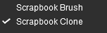 |
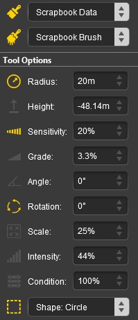
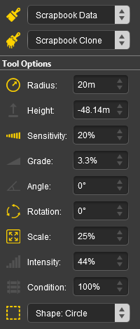
| Scrapbook Brush Actions: |
| Scrapbook Brush |
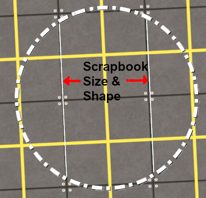
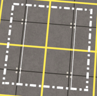
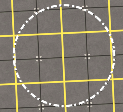
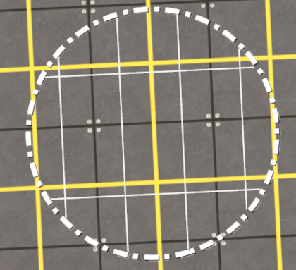
will resize the scrapbook contents to fit the Tool Options Palette Shape and Radius settings |
| Scrapbook Clone |
will paint the scrapbook sized according to the Tool Options Palette Scale and Radius settings. See Notes below |
|
|
|
|
Notes:
|
Scrapbook Brush will resize the scrapbook contents to fit the selected brush shape and size.
|
If the brush is small then the scrapbook contents will be compressed closer together |
|
If the brush is large then the contents will be spaced further apart |
|
Every Left Click will paste another complete scrapbook copy |
|
The Scale setting in the Tool Options Palette is ignored. |
|
Scrapbook Clone will paste the scrapbook sized according to the Tool Options Palette Scale setting (100% = original size)
|
If the brush is the same size as the scaled scrapbook then a single exact copy will be painted |
|
If the brush is smaller than the scaled scrapbook in size then only the central part of the scrapbook will be revealed and more will be added when the brush is moved around until the "painted" area covers the same area as the scaled scrapbook. Further painting will clone or tile the scrapbook contents |
|
If the brush is larger than the scaled scrapbook in size then the contents will be cloned or tiled to fill the set brush radius |
| See Using the Scrapbook Clone Brush below for examples and more information |
| |
 |
WARNING:
Take care if setting both the Scale and Radius . Using extreme values for both, such as a very large brush radius and a very small scale value, can cause performance issues (i.e. long delays) while the program attempts to scale and clone the scrapbook contents (see Using the Scrapbook Clone Brush for more details) |
|
|
|
Scrapbook Brush Tool Options
|
|
|
|
|
|
|
|
Notes: Tool Options Palette Controls
|
|
The active scrapbook brush options for each action are shown in the Tool Options Palette with a Gold coloured icon next to their names. Those options that have their icon greyed out will be ignored by the selected action, but they can still be edited. |
|
Most of the data entry boxes in the Tool Options Palette have a Popup Menu (Right Click inside the box) that can be used to collect and distribute data - see the Trainz Wiki Page How to Use the Surveyor 2.0 Palettes for more details. |
|
|
Notes:
|
|
Unlike Surveyor Classic, there is no upper limit to the brush Radius . Brushes of hundreds of metres (even kilometres) in size are possible. However, the performance will decrease as the brush radius increases. |
|
There is a lower limit to the brush Radius that is dictated by the baseboard resolution (10m, 5m or HD). For small brushes using the 5m and 10m Resolutions the scrapbook is not confined to the grid lines or intersections unlike small Ground Height and Ground Texture brushes. For the HD Resolution the minimum brush radius is 0.12m. |
|
Painting with a small brush size using the Scrapbook Brush target will compress the entire scrapbook into the brush size. |
|
Painting with the Scrapbook Brush
|
|
|
|
|
|
|
| Steps: To "paint" with a Scrapbook asset:- |
|
The minimum steps needed to paint the scrapbook currently shown as a thumbnail in the Scrapbook Palette are 1 2 3 and 7 . This will paint using the current settings in the Scrapbook Filter and the Tool Options Palette . The Scrapbook Palette does not have to be visible on the screen |
|
|
In the Tools Palette Left Click on the Brush Tool or press the W key |
|
select the Scrapbook Data target from the Brush Tool first drop down menu |
|
select a brush action ( Scrapbook Brush OR
Scrapbook Clone ) from the second drop down menu |
|
In the Scrapbook Palette select a Scrapbook asset to be painted (see The Scrapbook Palette below) |
|
In the Scrapbook Palette open the Scrapbook Filter and select the features to be painted and the method used (see Scrapbook Filters below) |
|
In the Tool Options Palette set any Brush controls such as the Radius |
|
Left Click or Left Click and Drag (depending on your brush selection in Step 3 ) on the terrain to paint with the scrapbook asset |
|
|
|
|
Notes:
|
|
Scrapbooks, when painted or pasted, can contain any combinations of:- |
|
Ground Heights |
|
Ground Textures |
|
TurfFX/Clutter Effect Layers |
|
Scenery Objects (Meshes) - individual buildings, trees, signals, etc |
|
Scenery Splines - roads, track, fences, etc |
| You have options in The Scrapbook Filters that will control which of these data types are added to your Trainz World and how they are added. |
|
|
|
Notes:
|
|
Unlike Surveyor Classic, there is no upper limit to the brush Radius . Brushes of hundreds of metres (even kilometres) in size are possible. However, the performance will decrease as the brush radius increases |
|
The Rotation control in the Tool Options Palette sets the starting angle for painting the scrapbook objects and you can adjust that angle in increments of 1° |
|
The [ and ] keys will rotate the angle for painting the scrapbook objects in increments of 10° BUT unlike painting with a Ground Texture you CANNOT hold down these keys to continuously rotate the brush while painting with a Scrapbook. The best option while painting is to periodically release the mouse, "tap" one of the rotation keys (each "tap" will rotate the brush by 10°) and then resume painting - repeat as necessary |
|
The Ground Height options in the Scrapbook Filters controls how the terrain heights in the Scrapbook are applied. The Height setting in the Tool Options Palette will be ignored |
|
Setting extreme values for the Scale and Radius when using the Scrapbook Clone brush action can cause performance issues (i.e. long delays, even "freezing") while the program attempts to scale and clone the scrapbook contents into the route (see Using the Scrapbook Clone Brush for more details) |
|
|
|
If you have set the Ground Height Scrapbook Filter Option to Add or Overwrite (see Scrapbook Filters below) then the rate or speed at which the ground height changes will be controlled by the Tool Options Palette Sensitivity setting
|
|
Sensitivity Settings:
|
1% for the smallest possible change with each sweep of the brush |
|
100% for the largest possible change with each sweep of the brush |
| Values between these two limits will give intermediate changes with each sweep of the brush over the same area |
|
|
|
|
Using the Scrapbook Clone Brush
|
|
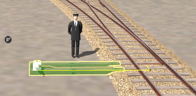
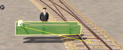
When using the Scrapbook Clone brush its Radius and Scale settings in the Tool Options Palette are important. |
|
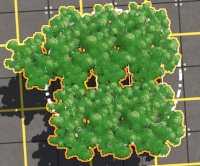
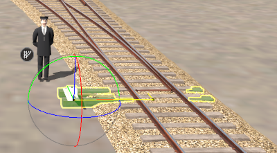
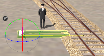
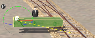
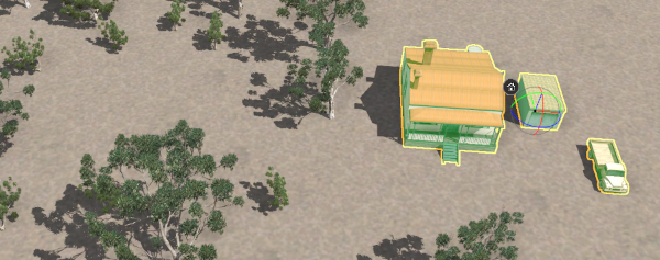
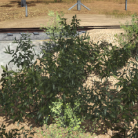
For Example: Two trees as shown below are captured as a Scrapbook with a size of 2x1 baseboard squares.
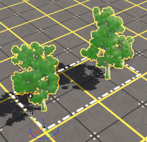 |
|
When Using the Clone Brush Remember:
|
|
|
|
The Brush Tool target is set to Scrapbook Data and its action set to Scrapbook Clone. The effects of different Radius and Scale settings in the Tool Options Palette are shown below.
|
|
Scrapbook Painting Tips
|
|
|
|
|
|
|
|
Add Variety to Painting a Scrapbook
| A single scrapbook can be reused many times in a layout but each instance can have variations that will make it different from the others. Use the following techniques:- |
|
| Steps: To add variety to Painting a Scrapbook:- |
|
Use the Scrapbook Filters to change the elements that are placed into the route (e.g. Ground, Scenery, Textures, Splines, Effect Layers) and how they are added (None, Add, Overwrite) each time it is painted |
|
In the Tool Options Palette alter the Scale and Rotation settings . This works best when the Ground Height and Effect Layers scrapbook filter options have been set to None |
|
| |
| Steps: To avoid repetition patterns forming when painting with a scrapbook:- |
|
Press the [ or ] rotation keys between mouse clicks or brush strokes. Each key press will rotate the brush by ±10°. NOTE: Unlike painting a ground texture, you cannot hold down these keys while painting with a scrapbook . The best option while painting is to periodically release the mouse, "tap" one of the rotation keys (each "tap" will rotate the brush by 10°) and then resume painting - repeat as necessary. |
|
| |
|
|
Caution: When switching between the Ground Texture and the Scrapbook Data Brush Tools |
|
|
ALWAYS check the Tool Options Palette Scale setting before painting with the Scrapbook Clone action. If the Scale is set to a very small value then Trainz may freeze while attempting to scale and clone the scrapbook. |
| |
|
Using the Scrapbook Brush as an "Eraser" |
| You can replace the objects that have been painted into an area using one scrapbook (or simply added with the Placement Tool) with the objects in another scrapbook in a simple replacement operation. This can be extended to create an eraser that will remove ALL objects from an area. |
| Steps: To perform a replace/erase operation:- |
|
Select a replacement scrapbook from the Scrapbook Palette . If you are using the second scrapbook as a "eraser" then pick one with just a few simple items, for example grasses and/or small bushes if possible |
|
Set the required Filter(s) (e.g. "mesh", "spline", etc) in the Scrapbook Palette to Overwrite . Set the other filters as needed. |
|
In the Tool Options Palette set the Radius to a suitable value. If you are using the scrapbook as an eraser then set the Scale to a ridiculously high value, such as 10000%. |
|
Use a painting action to paint over the area or areas covered by the objects to be removed/replaced. Take care around the edges to avoid replacing other objects |
|
|
The Scrapbook Palette
|
|
|
|
|
|
|
|
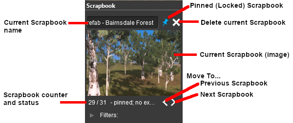
This palette selects the scrapbook to be painted or pasted as well as performing a very limited range of management tasks |
 |
  |
Left Click on the pin icon to Lock (blue pin) and Unlock (white pin) the scrapbook. Locked scrapbooks are permanent (but can still be deleted). Unlocked scrapbooks will "expire" (self delete) after 5 days |
 |
Left Click on the delete icon to delete the current scrapbook - most scrapbooks can be deleted (see Notes: Deleting Built-in Scrapbooks below on how to deal with the exceptions to this)
|
Deleting a scrapbook WILL NOT delete any objects that it has painted or pasted into the route. The scrapbook simply identifies the objects, it has no control over them after they have been added to the route. |
|
 |
The thumbnail of the currently displayed scrapbook and the one that will be painted or pasted into the route |
 |
Identifies the currently displayed scrapbook (the first number) and the total number of stored scrapbooks (the second number) |
 |
Left Click on the < or > to move forwards or backwards through the stored scrapbooks to select the scrapbook that will be added to the route. A scrapbook will be selected when its name and thumbnail appear in the palette |
| |
The scrapbook name can be edited. Simply Left Click inside the name box to edit or replace the current name then Left Click on the image OR press the Enter key to confirm the edit |
|
|
|
Notes: Deleting Built-in Scrapbooks
|
| Some scrapbooks are installed with Trainz and cannot be deleted. These scrapbooks have the label Prefab at the front of their names (you may have to scroll to the front of the name to see it). While they cannot be deleted they can be "disabled" so that they won't appear as an installed scrapbook. Unlocking them will not cause them to "expire" - after 5 days they will just become locked again. |
| Steps: To disable built-in scrapbooks |
|
Open Content Manager and locate the "permanent" scrapbook or scrapbooks.
Search Tips: Name: starts with "Prefab"; Status: is Built-in; Type: is Misc |
|
Highlight (select) the scrapbook assets individually or as a group |
|
Open the Content menu and select the Disable option |
You can reverse this and enable any or all of these scrapbooks at any time if you need them. When enabled they will reappear in the palette |
|
|
The Scrapbook Filters
|
|
|
|
|
|
|
|
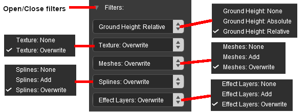
The filters control which elements in the scrapbook are added to the route and how they are added. |
| Step: To Open the Scrapbook Filters |
|
Left Click on the arrowhead next to the Filters: label below the scrapbook image to open the scrapbook filters. |
|
|
This Brush Target paints a selected Effect Layer into your Trainz World. The name of the selected layer will appear next to the Brush Tool icon |
|
You must have Effect Layers already installed in Surveyor for this Brush Target to be selected. |
|
|
Effect Layers allow you to create and add special scenery effects to your Trainz World. Depending on your Trainz version, operating system and hardware there are four different types of Effect Layers you can add:- |
|
|
TurfFX - only available for Nvidia graphic cards and Windows systems . TurfFX consists of 3D animated (e.g. swaying in a breeze) plants that can be used to cover areas of terrain. An example would be a wheat crop. TurfFX layers are painted onto the terrain like a texture and will follow the terrain shape. You can have multiple TurfFX layers. |
|
Clutter - similar to TurfFX but restricted to smaller objects such as ground cover plants and small rocks. Clutter layers are painted onto the terrain like a texture and will follow the terrain shape. You can have multiple Clutter layers. |
|
Water - when added a Water Effect Layer will cover the entire layout and will normally sit below the terrain surface (default height is 0m). Areas of a water layer can be raised up to become visible to form a stream, lake, pond or an ocean. You can have multiple water layers each with different water colours and surface effects (calm, ripples, stormy). |
|
Color - only available in Trainz Plus when using HD Terrain. The Color Layer allows you to add color tints and lightening/darkening effects to different areas of the terrain. The Color Layer sits on the terrain surface but is only visible when it is painted if its default color has been set to neutral grey (0.500 - see Edit Effect Layers below). Only a single Color Layer can be added but it can be painted with different colour effects in different areas. |
|
|
Notes:
|
|
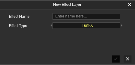
Effect Layers are created using the Edit Effect Layers options found in both the  Surveyor Edit Menu at the top of the screen and also in the Brush Tool Action Drop Down Menu. They can also be loaded from .cdp files and installed from the DLS (Download Station) Surveyor Edit Menu at the top of the screen and also in the Brush Tool Action Drop Down Menu. They can also be loaded from .cdp files and installed from the DLS (Download Station) |
|
Once created Effect Layers can be saved as Presets to be used in other routes |
|
|
|
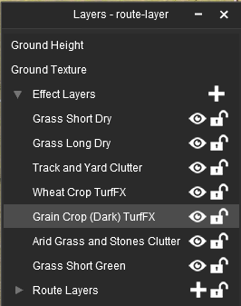
Each effect layer that you add or create will be saved as a seperate layer in the Effect Layers Group in the Layers Palette |
|
|
The Effects Layer Group cannot be renamed, deleted, moved or merged with any other layer |
|
Individual effect layers can be renamed, deleted and edited, but not moved or merged with any other layer group |
|
All effect layer edits are performed using the Brush Tool, or by selecting the layer in the Layers Palette , or from the Surveyor Edit Menu |
|
Selecting an Existing Effect Layer
|
|
|
|
|
|
|
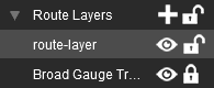
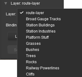
| Effect Layers that you have created for the current route (see Edit Effect Layers) or installed into the current route (see Loading Preset Effect Layers) will be listed in both the Layers Palette and in the Brush Tool Action Drop Down Menu. |
Selecting an Effect Layer from the Brush Tool:
Selecting an Effect Layer from the Layers Palette:
Loading Preset Effect Layers
|
|
|
|
|
|
|
|
Preset effect layers are layers that have been created in other routes and saved into Content Manager or downloaded from the DLS |
|
Preset effect layers can be added to your existing route |
For instructions on saving an effect layer as a Preset, see Save a Layer as a Preset below.
|
The quickest method of loading a Preset into a route is to use the Filter Palette and Assets Palette . Both must be visible on your screen. |
|
| Steps: To load a Preset into a route:- |
|
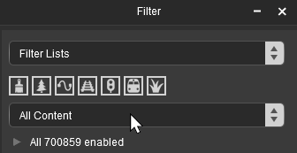
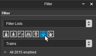
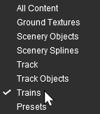
In the Filter Palette select the Presets icon  (the last icon in the list) or select Presets from the Content Drop Down Menu below the icons (the last icon in the list) or select Presets from the Content Drop Down Menu below the icons |
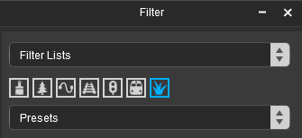 |
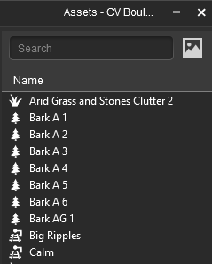
The Assets Palette display is controlled by the selections made in the Filter Palette . Selecting Presets in the Filter Palette the Assets Palette will display a list of all the installed effect layers. For more information about the Assets Palette see the Trainz Wiki Page How to Use the Surveyor 2.0 Palettes - Assets Palette |
|
|
|
|
Effect Layer Tool Options
|
|
|
 |
|
|
|
|
You can control how an effect layer is painted into your Trainz World through the settings in the Tool Options Palette |
|
The Effect Layer brush tool uses the Tool Options Palette . If this palette is not visible on the screen then refer to Notes: Palettes at the top of this document. |
|
|
Notes: Tool Options Palette Controls
|
|
The active effect layer brush options for each action are shown in the Tool Options Palette with a Gold coloured icon next to their names. Those options that have their icon greyed out will be ignored by the selected action, but they can still be edited. |
|
Most of the data entry boxes in the Tool Options Palette have a Popup Menu (Right Click inside the box) that can be used to collect and distribute data - see the Trainz Wiki Page How to Use the Surveyor 2.0 Palettes for more details. |
|
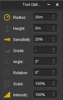
| Radius |
the brush radius (metres) |
| Range: |
Will depend on the effect layer being added. See Notes: below |
|
| Height |
Water Effect Layer only - the height of the layer (in metres) as painted by the brush |
|
|
| Sensitivity |
the rate at which the Intensity (TurfFX, Clutter, Color) or Height (Water) setting changes under the brush |
| Range: |
1% (very slowly) to
100% (very quickly) |
|
| Intensity |
effect density or coverage within the brush |
| Range: |
1% (almost none) to
100% (maximum) |
|
| Grade |
Water Effect Layer only - the slope gradient. See Notes: below |
| Range: |
0% (flat) to
±100% (steep but not vertical) |
|
| Angle |
Water Effect Layer only - the grade direction (compass degrees) |
| Range: |
0° (North) to ±359°
a negative value reverses the grade direction |
|
| Color |
Color Effect Layer only - the colour selection (RGB and Brightness values) - in Trainz Plus only and it will only be visible when HD Terrain is being used |
| Range: |
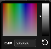 |
Left Click on the coloured box next to the title Color to open the colour selector.
Set a Colour: Select a colour by either:- |
|
a Left Click on the colour in the colour picker device, OR |
|
enter its RGB value in Hexadecimal |
| Optionally: Set a brightness value for the selected colour by moving the slider up or down |
| Reset: Left Click the Reset button (the circular arrow on the bottom right) to cancel your changes and reset the colour to its default value. This default value is set using the Edit a Color Effect Layer controls shown below |
|
|
|
|
The Height setting is ignored for TurfFX, Clutter and Color effect layers because these layers will be painted at the existing ground surface height. |
|
|
|
Notes:
|
|
Unlike Surveyor Classic, there is no upper limit to the brush Radius . Brushes of hundreds of metres (even kilometres) in size are possible. However, the performance will decrease as the brush radius increases |
|
The minimum brush Radius for a TurfFX and Clutter Effect Layer will depend on its configuration settings - the asset density, the resources used, etc. This minimum size will be different for different Effect Layers. If the Radius value is below the required minimum for the selected TurfFX or Clutter Effect Layer then the brush circle will turn RED and it will not paint |
|
The Grade is defined as vertical rise divided by horizontal distance converted to a percentage figure. So a grade of 100% (the maximum allowed) would mean a slope formed by the height and distance both being the same value (e.g. a height increase of 50m over a distance of 50m). A vertical slope (a cliff) would have an infinite grade (cliff height divided by 0) which is currently impossible in Surveyor. |
|
|
TurfFX and Clutter Effect Layers
|
|
|
|
|
|
|
|
TurfFX and Clutter are Effect Layers that can quickly add vegetation and other ground "artifacts" (e.g. weeds, crops, stones, etc) over large areas |
|
In a future "soon to be released" TM version of Trainz, TurfFX will be removed as a separate effect layer and become part of an updated Clutter effect layer |
|
CAUTION: |
The TurfFX Effect Layer is:-
|
an Nvidia product (it is not from N3V) and requires the presence of an Nvidia GPU such as a GTX or RTX video graphics card. The TurfFX Effect Layer will not appear on systems that do not have an Nvidia video card |
|
only supported on MS Windows. It will not work on MacOS systems |
|
|
|
This section covers using an existing TurfFX or Clutter effect layer.
For information on creating TurfFX or Clutter effect layers see Edit Effect Layers below |
|
| Brush Actions |
When a TurfFX or Clutter Effect Layer has been selected as the Target, the second drop down box will give a choice of three actions. |
|
| The actions are:- |
|
Increase |
|
Decrease |
|
Set Intensity |
|
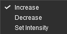 |
|
Use the Tool Options Palette Intensity and Sensitivity settings to control how the Effect Layer is applied to the terrain by the brush |
|
|
|
| TurfFX and Clutter Effect Layer Actions: |
| Increase |
increases the Tool Options Palette Intensity of the effect layer at a rate controlled by the Sensitivity setting, upto a maximum of 100%. Each time the brush is moved over the same area the Intensity or Density of the effect layer is increased |
| Decrease |
decreases the Tool Options Palette Intensity of the effect layer at a rate controlled by the Sensitivity setting. Each time the brush is moved over the same area the Intensity or Density of the effect layer is decreased |
| Set Intensity |
will paint the effect layer in one sweep using the full Tool Options Palette Intensity setting |
|
|
|
Notes:
|
|
The density or coverage of the TurfFX and Clutter ground effects within the brush area is controlled by the Tool Options Palette Intensity setting.
|
|
Intensity Settings:
|
1% to apply the effect very lightly |
|
100% to apply the effect at full density |
| Values between these two limits will give intermediate changes with each sweep of the brush over the same area |
|
|
|
|
The rate or speed at which the TurfFX and Clutter ground effects change when using the Increase or Decrease brush actions is controlled by the Tool Options Palette Sensitivity setting.
|
|
Sensitivity Settings:
|
1% to increase/decrease the application of the ground effect very slowly when you move the brush |
|
100% increase/decrease the application of the ground effect at the maximum possible rate when you move the brush |
| Values between these two limits will give intermediate changes with each sweep of the brush over the same area |
|
|
|
|
|
Notes: "Floating Turf"
When painting with a TurfFX Effect Layer or a Clutter Effect Layer brush, care must be taken when near the edge of the route. Painting over the edge will create "floating" effect layer artifacts. This can occur in both Surveyor 2.0 and Surveyor Classic. The same effect will occur if an effect layer is painted over a dig-hole, such as those used at tunnel entrances. |
|
|
Water Effect Layer
|
|
|
|
|
|
|
|
The Water Effect Layer will cover the entire route but different parts can be raised above the ground to reveal the water where required |
|
| A Water Effect Layer will always be added when a new route is created |
|
|
You can have more than one Water Effect Layer each with a different colour and/or surface effect (calm, ripples, rough) to simulate different water features (e.g. pond, lake, stream, ocean) |
|
The Ground Height can also be raised or lowered to hide and reveal the water layer where required |
|
This section covers using an existing Water Effect Layer.
For information on creating a Water Effect Layer see Edit Effect Layers below |
|
| Brush Actions |
When a Water Effect Layer has been selected as the Target, the second drop down box will give a choice of five actions. These actions are identical to those found in the Ground Height Target plus a new action:- |
|
| The actions are:- |
|
Height Up |
|
Height Down |
|
Set Height |
|
Grade |
|
Bulk Adjust |
|
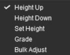 |
|
Use the Tool Options Palette Sensitivity Height Grade and Angle settings to control how the Water Effect Layer is applied |
|
|
|
| Water Effect Layer Actions: |
Height Up
Height Down |
raises/lowers the water layer at a rate controlled by the Tool Options Palette Sensitivity setting |
| Set Height |
will "plateau" the water level to the Tool Options Palette Height setting at a rate controlled by the Sensitivity setting |
| Grade |
creates a smooth water slope at the Tool Options Palette Grade and Angle settings at a rate controlled by the Sensitivity setting - see Notes: below |
| Bulk Adjust |
will move the entire water layer up or down - see Notes: below |
|
|
| Steps: To paint with a Water Effect Layer:- |
|
You can jump directly to Step 3 by selecting the named Water Effect Layer in the Layers Palette |
|
|
In the Tools Palette select the Brush Tool or press the W key |
|
select the <water effect layer name> from the Brush Target drop down menu. If there are no Water Effect Layers listed then none have been created or installed for this route |
|
select a Brush Action from the second Drop Down Menu ( Height Up , Height Down , Set Height , Grade or Set Bulk Adjust ) |
|
In the Tool Options Palette set any required Brush settings - Radius , Height , Sensitivity , Grade and Angle |
|
The colour and surface effect (calm, ripples, rough) of a Water Effect Layer are set in its properties (see Water Layer Edit Controls below) |
|
|
Left Click or Left Click and Drag on the terrain to paint with the Effect Layer |
|
|
|
|
|
|
Notes:
|
|
It is NOT recommended that you use both Water Effect Layers and the original Legacy Water in the same route. Use one or the other but, where possible, avoid using both. |
|
The Grade setting is the vertical rise divided by horizontal distance converted to a percentage figure. So a grade of 100% (the maximum allowed) would mean a slope formed by the height and distance both being the same value (e.g. a height increase of 50m over a distance of 50m). A vertical slope (e.g. a waterfall) would have an infinite grade (cliff height divided by 0) which is currently impossible in Surveyor. |
|
The Bulk Adjust brush action is not fully intuitive and will require some experimentation. It will raise and lower the water effect layer in the baseboard where the Left Click and Drag was executed. Areas within that baseboard where the water effect layer had previously been set to a different height will not be affected until the water level reaches the same height. The Water Effect Layer in surrounding baseboards will also start to move when the level reaches their current heights. Also note that the speed at which the layer moves up or down will decrease as the size of the route increases. In a very large route there may not be any noticeable movement at all. In this case it may be easier to delete the Water Effect Layer and create another one at the new height |
|
|
Water Effect Layer Example
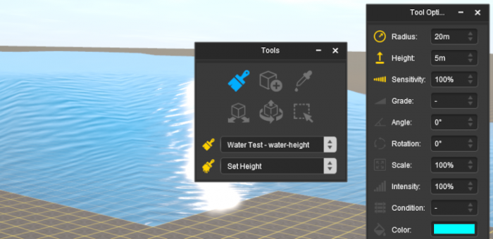 |
A water layer has been lifted above the terrain by using the Tools Palette :-
|
The Brush Target is set to the selected Water Layer |
|
The Set Height action has been selected from the second drop down menu |
| ... and |
|
The Tool Options Palette Height is set, for example, to a few metres above the terrain height |
The brush painting action is then used to paint the water at the set height. |
Water Effect Layer Tips
|
|
|
|
|
|
|
|
The first step with using a Water Effect Layer is to create it at the correct height
See Edit a Water Effect Layer below for the details on creating a Water Effect Layer.
|
When you create a new Water Effect Layer it will cover the entire route at the default height of 0 metres. Depending on the starting height of your route (which is set in the very first baseboard) this may be too high and place the water layer above the route and drown everything. |
|
Once you create a Water Effect Layer its height cannot be altered by editing its properties (see Edit a Water Effect Layer below) and the Bulk Adjust option in the Brush Actions for the Water Effect Layer is extremely slow and inefficient when used on large routes. |
|
If you have created a Water Effect Layer at the wrong height then the best solution may be to delete it and create a new layer at the correct height |
| Steps: When creating a new Water Effect Layer:- |
|
Locate the lowest ground height in your route. Take note of its altitude by placing the Compass on the lowest spot and read its height value in the Info Palette |
|
Set the default water height in the Water Effect Layer Edit Properties window to slightly below (e.g. 1, 2 or 3 metres below) that height. If the minimum ground height is above 0 metres then you can safely leave the default height at 0 metres |
|
|
|
|
|
To create a flat water layer at a set height use the following technique:-
| Steps: To Create a Flat Water Surface:- |
|
Select the Water Effect Layer in the Layers Palette. This will also select that same layer in the Brush Tool |
|
In the Tools Palette select the Set Height brush action rather than Height Up/Height Down actions |
|
In the Tool Options Palette set the Height to the required value so that the water will be visible above the ground surface and the Sensitivity to 100% |
|
Paint with the brush to bring the Water Effect Layer up to the set height |
|
|
|
To create a sloping water layer use the following technique:-
|
Select the Water Effect Layer in the Layers Palette. This will also select that same effect layer in the Brush Tool |
|
In the Tools Palette select the Grade brush action |
|
In the Tool Options Palette set the Grade and the Angle to the required values |
|
Paint with the brush to create the Water Effect Layer surface at the set gradient adjusting the slope direction ( Angle ) when required |
|
|
Color Effect Layer
|
|
|
|
|
|
|
|
The Color Effect Layer is only available to Trainz Plus subscribers and is only visible in routes using HD resolution |
|
The Color Effect Layer adds a "colour tinting effect" to selected areas of the route |
|
Only one Color Effect Layer can be added to a route and it will cover the entire route but it can have different colours in different parts of the route |
|
This section covers using an existing Color Effect Layer.
For information on creating a Color Effect Layer see Edit Effect Layers below |
|
| Brush Actions |
When the Color Effect Layer has been selected as the Brush Target, the second drop down box will be blank as there are no brush actions for this effect layer. |
|
| You can think of the Color Effect Layer as a "skin" that covers the ground throughout the layout. If the three colour (RGB) Default values in the layer have all been set at 0.500 (see Color Layer Edit Controls below) then the "skin" will be transparent and you can add different colours (or "tints") at different places to alter the appearance of the ground textures. |
|
Notes:
The Color Effect Layer is only available in routes using HD Resolution. You can add the effect layer to a route that uses 5m Resolution and/or 10m Resolution but the layer will only appear if the route is converted to HD Resolution |
|
|
Painting a Color Effect Layer |
|
| The Color Effect Layer is painted in the places where it is needed using the Brush Tool in the same way that you would paint a ground texture. The same restrictions that apply to painting a ground texture also apply to painting a Color Effect Layer. |
|
the minimum brush size you can use for unrestricted painting is 5m |
|
you can use smaller brush sizes but there will be restrictions on where you can paint. These restrictions are explained at Ground Texture in 5m/10m Resolutions |
|
| No color effect layer applied |
Color effect layer applied |
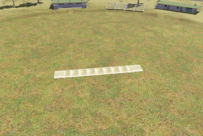 |
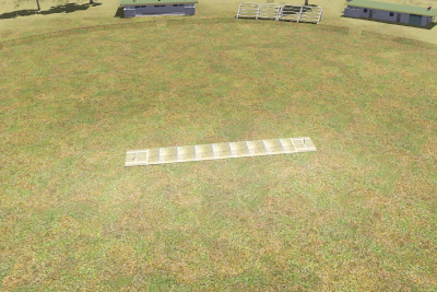 |
| Cricket pitch scene before and after applying a color effect layer that gives the impression of "wear and tear" around the pitch area |
| When this Brush Target is selected, the Edit Effect Layer dialogue box will appear. This is the same as selecting Edit Effect Layers ... from the Surveyor Edit Menu. |
| Brush Actions |
When the Edit Effect Layers... Target is selected, the second drop down box will be disabled - there are no actions for this brush target. |
|
You will have only one available option if no Effect Layers are present in Surveyor or two options if Effect Layers are present.
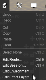 |
Option Create a New Effect Layer
| If no Effect Layers are present then you can create a new one |
|
|
|
Save a Layer as a Preset
|
|
|
|
|
|
|
|
A Preset is an edited or created effect layer that has been saved so that it can be reused in other routes |
| Once an effect layer has been created or edited, it can be saved and will appear as a new asset in Content Manager. It can be loaded into other routes (see Loading Preset Effect Layers above), saved as a .cdp file and uploaded to the DLS. |
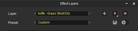 |
| Steps: To save an effect layer as a Preset:- |
|
Open the Effect Layers window and select the effect layer to be saved |
|
Left Click on the  icon. The effect layer will be saved using the name you entered for the layer (Grass Short Dry in the example shown on the left) icon. The effect layer will be saved using the name you entered for the layer (Grass Short Dry in the example shown on the left) |
|
|
|
Notes:
A Preset can be deleted from the current route ( Left Click on the  icon) but it will remain as a saved asset in Content Manager and can be reloaded if needed. To permanently delete a preset it must be deleted using Content Manager icon) but it will remain as a saved asset in Content Manager and can be reloaded if needed. To permanently delete a preset it must be deleted using Content Manager |
|
TurfFX Layer Edit Controls
|
|
|
|
|
|
|
Clutter Layer Edit Controls
|
|
|
|
|
|
|
Water Layer Edit Controls
|
|
|
|
|
|
|
|
The Water Effect Layer has been introduced mainly for Surveyor 2.0 although an older and more restricted version is available in TRS19 SP4 |
| In Surveyor 2.0 you can have more than one Water Effect Layer. Each can have a different combination of water colour and surface effects (calm, ripples, rough). Each can be raised above the ground height to present a different water surface in different locations. |
Color Layer Edit Controls
|
|
|
|
|
|
|
|
The Color Effect Layer is only available to Trainz Plus subscribers |
|
It can only be used in routes built with HD Resolution |
| You can only have one Color Effect Layer but through the Tool Options Palette it can be given different colours in different locations. |
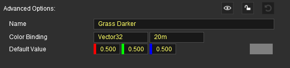 |
|
WARNING:
Always edit these values with caution |
|
only one color effect layer can be added to a Route |
|
the color effect layer only works when using HD resolution |
|
|
|
|
If you leave the default RGB colours at 0.500 then the colour layer will be invisible except in those areas where you have applied a colour |
|
 |
Keyboard Shortcut: E |
|
|
The Placement Tool adds selected assets to a Trainz World |
|
Various function of this tool use the Tool Options Palette Layers Palette Info Palette Filter Palette and the Assets Palette . If these palettes are not visible on the screen when required then refer to Notes: Palettes at the top of this document. |
|
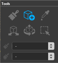 |
| Tool Targets The Placement Tool has no Target options so it has no drop down menu list |
|
When selected, this tool has a distinctive pointer icon which makes it easy to identify that the Placement Tool is active  |
|
Selecting an asset in the Assets Palette or an effect layer in the Layers Palette will automatically activate the Placement Tool |
|
| Tool Actions The Placement Tool has no Action options so it has no drop down menu list |
|
The Placement Tool is used for adding the following objects to a route:- |
|
|
|
More Placement Options |
| After an object has been placed in a route its position and/or height can be changed by choosing one of the following:- |
| Options: |
|
using the Free Move Tool OR |
|
using the Fine Adjustment Tool OR |
|
editing its x: y: z: settings in The Info Palette OR |
 |
selecting the Apply Height option in its Context Menu. This will apply the Height value stored in the Tool Options Palette to the object |
|
Placement: Setting an Objects Name and Layer
|
|
|
|
|
|
|
|
All scenery objects can be given names and can be assigned to layers |
|
|
For some objects a name is needed for the operation of a Session but for most objects a name is optional. |
|
At the very basic level the layer assigned to an object will decide whether it is saved as part of the Route or as part of a Session. |
|
Setting an Objects Name
|
|
|
|
|
|
|
|
Object names are optional but for some objects they are essential for running a session |
| You can give any object in your route an identifying name. In some cases a name is vital for AI and session operations, in other cases it will be needed as a display feature - for example: to be shown on a station nameboard. A name also makes it easier to search for a particular object using the Find Tool ( Ctrl + F keys). You must have an object selected (highlighted) before it can be named - for example immediately after it has been added to a layout by the Placement Tool |
|
If the Info Palette is not visible on the screen then refer to Notes: Palettes at the top of this document. |
|
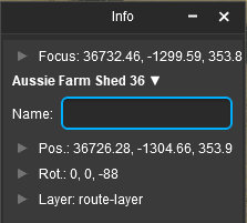 |
| Steps: To name (or rename) an object:- |
|
In the Info Palette Left Click inside the Name: text entry box |
|
If the Name: text entry box is greyed out and cannot be selected then the layer containing the object is locked. Use the Layers Palette to unlock the layer (see The Layers Palette), reselect the object and try again |
|
|
Enter or edit the name |
|
Press the Enter key |
 |
KNOWN BUG: Changes to the name of a Track Object will not save unless something else in the route is also edited. The following additional step is a workaround when renaming Track Objects |
|
If renaming a track object then move a non-track object (e.g. a tree) before saving. If you have already edited something else in the route but not yet saved then this step will not be necessary |
|
|
Setting an Objects Layer
|
|
|
|
|
|
|
|
All objects in the Trainz World are in layers. For scenery objects you can set and change the layers where they are placed |
|
Layers are an essential feature of Trainz for managing different objects in Surveyor. Layers can be:- |
|
|
locked to prevent the accidental deletion, movement or alteration of the objects they contain |
|
hidden to remove their objects from view so that other nearby objects can be manipulated |
| Layers can also be used in Driver to hide and reveal objects during gameplay. |
|
|
More information on creating, editing and using Layers can be found on the Trainz Wiki Page at:-
|
|
|
| An object will always be placed in the currently set Active Layer. The active layer can be changed before the object has been added and objects can be moved to different layers at any time. |
|
If the Layers Palette and the Info Palette are not visible on the screen then refer to Notes: Palettes at the top of this document. |
|
|
After an object has been placed into a layer in the Trainz World it can be moved to a different layer |
| If an object is still selected (highlighted) by the Placement Tool then you can change its assigned layer as often as you like. If it is not selected then you must first select it using either the Free Move Tool or the Fine Adjustment Tool. |
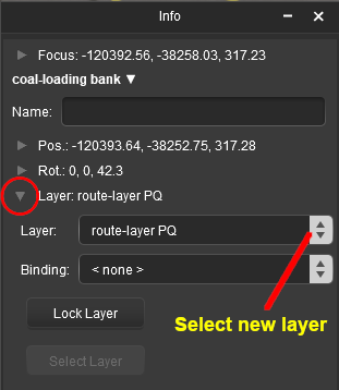 |
| Steps: To move a placed object to another layer:- |
|
In the Info Palette Left Click on the Layer arrowhead icon (circled in red in the image left). This will open up the layer controls for the selected object |
|
the drop down menu box labelled Layer shows the currently assigned layer for that object. Left Click on the Up/Down arrows to open the list of all available layers. |
|
select the destination layer from the list. The object will then be moved to the selected layer - you will be given a warning if the move has failed (usually because the objects layer is locked) |
|
Also see:-
|
|
|
|
|
CAUTION: Take Care when assigning objects to layers |
|
Placing an object in the Route Layer Group will save it in the Route and it will appear in every Session based on that Route |
|
Placing an object in the Session Layer Group will save it in the Session and it will only appear in the currently loaded Session |
|
Placement: Scenery Mesh Objects
|
|
|
|
|
|
|
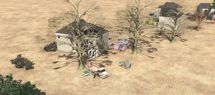
Typical Scenery Mesh Objects
Buildings, trees, bushes, vehicles, people, "clutter" |
Placement: Add a Scenery Mesh Object
|
|
|
|
|
|
|
|
Individual "non-spline" scenery objects that are not attached to track are often referred to in Trainz terminology as Scenery Mesh Objects. |
|
Scenery Mesh Objects include single (non-spline) scenery items such as buildings, trees, road signs, cars (non moving), people and animals |
|
If the Filter Palette and Assets Palette are not visible on the screen then refer to Notes: Palettes at the top of this document. |
|
| Steps: To add a Scenery Mesh Object the first step is to identify the exact asset you want to add. |
|
In the Filter Palette choose one of the following:-
|
|
In the Filter Palette the Scenery Objects icon will be shown in blue when it is selected and the name Scenery Objects will appear in the drop down box below the icons. For more information about the Filter Palette see the Trainz Wiki Page How to Use the Surveyor 2.0 Palettes - Filter Palette |
|
The Assets Palette display is controlled by the selections made in the Filter Palette . Selecting Scenery Object in the Filter Palette will produce a list of all the installed Scenery Objects in the Assets Palette . For more information about the Assets Palette see the Trainz Wiki Page How to Use the Surveyor 2.0 Palettes - Assets Palette |
|
|
In the Assets Palette you have the option to narrow down the filtered list. Type the assets name or part of the name into the Search box. For example if you have selected Scenery Objects and want to find "wooden barns", then type "wooden barn" (UPPER/lower case does not matter) - the part names "wooden" or "barn" would also work but will produce longer lists.
This will list all the Scenery Objects containing the text "wooden barn" in their names or descriptions. |
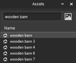 |
|
In the Assets Palette Left Click on the required item in the list. When selected the asset will be highlighted with a light grey background. |
|
Notes:
A Left Click on an asset in the Assets Palette filtered list will automatically activate the Placement Tool so the next Left Click will place that asset in your Trainz World. |
|
|
|
Content Manager in a Palette
|
| The Assets Palette can be expanded to provide more information, like in Content Manager, about each listed asset. |
Placement: Move a Scenery Mesh Object
|
|
|
|
|
|
|
| Warning: |
|
To move a scenery mesh object DO NOT click on it with the Placement Tool as this will just add another object |
|
Placement: Delete a Scenery Mesh Object
|
|
|
|
|
|
|
To delete a scenery mesh object (or any object) that has just been added by the Placement Tool and is still highlighted, choose one of the following:-
Options: |
|
press the Delete key, OR |
|
open its Context Menu ( Left Click on its icon or press the T key) and select the option Delete |
|
If the object is not highlighted then you must first switch to either the Free Move Tool or the Fine Adjustment Tool, select the object and then choose one of the above options |
|
|
Placement: Set the Height of a Scenery Mesh Object
|
|
|
|
|
|
|
|
An object that has just been added to a route using the Placement Tool can have its height adjusted immediately after placement |
|
or it can be adjusted at a later time using the Free Move Tool or the Fine Adjustment Tool |
|
If the Tool Options Palette is not visible on the screen then refer to Notes: Palettes at the top of this document. |
|
Get the Height of a Scenery Mesh Object
|
You can copy the height of a selected scenery mesh object (e.g. a house) into the Tool Options Palette Height setting while the Placement Tool is still active. Once it has been copied it can be applied to any other object.
| Steps: To copy the height of any selected object into the Height setting:- |
|
In the Tool Options Palette Right Click in the Height setting |
|
select the Get Height from Selection option |
|
| |
| You can check the height of any selected object or endpoint using the Info Palette . The height is the last value in the Pos: (Position) data set. |
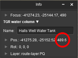 |
|
|
Set the Height of a Scenery Mesh Object
In Surveyor 2.0 scenery mesh objects can be given a height that can place them above or below the ground level.
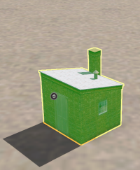 |
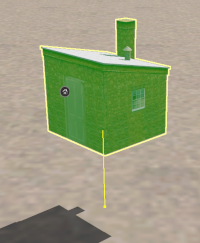 |
To set the height of a selected scenery mesh object, choose one of the following:-
Options: |
|
In the Tool Options Palette Height setting, enter a value followed by the Enter key OR |
|
In the Tool Options Palette Height setting, enter a value then Right Click and select Set Height to Selection OR |
|
from the objects Context Menu select the Apply Height option to apply an existing height setting, OR |
|
in the Info Palette enter a value in the objects Pos: z: (height) setting or Left Click and Drag Up or Down on the double arrowheads to its right. This can be used to set the height to cm accuracy (see The Info Palette below). |
|
All heights are relative to where an object is placed. Heights are not absolute. If an object is placed 1 metre above the surface, for example, and is then moved along a slope it will always keep its height the same 1 metre above the surface at every point of the slope |
|
|
|
| The object will be moved to the set height above (or below) the terrain. The vertical yellow line shown in the second image on the left indicates the height change. The small yellow dot at the base of the line is the terrain attachment point for the object. |
Placement: Configure an Industry Object
|
|
|
|
|
|
|
|
Some scenery mesh objects have been designed as Industry Objects that can produce and/or consume products |
|
These objects can be preset to process specific products and quantities when a Session starts |
|
Scenery Mesh Object Context Menu Options
|
|
Once a scenery mesh object has been placed you can open its Context Menu ( Left Click on its icon or press the T key) to access a range of options and functions. The following Scenery Mesh Object specific options will appear, along with other more general options, in the objects Context Menu.
|
| Apply Height |
sets the height of the selected objects to the value in the Tool Options Palette Height setting |
|
| Reset Object Rotation |
resets the rotation angle of the selected objects to their default values |
|
| Randomise Object Rotation |
applies a random rotation angle to each selected object around its vertical axis |
|
| See Free Move: Scenery Mesh Object Context Menu for the full list of Context Menu options for Scenery Mesh Objects. |
|
Placement: Spline Objects (Including Track)
|
|
|
|
|
|
|
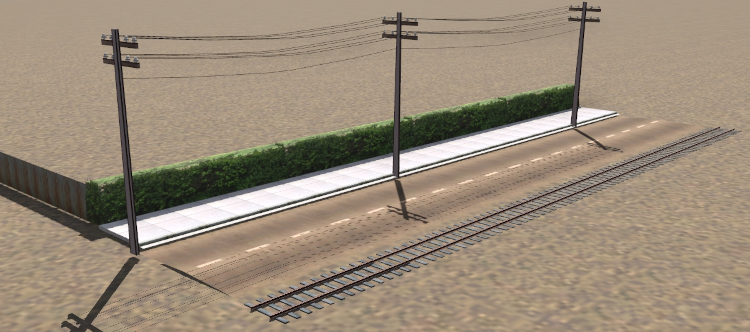
Typical Spline Objects
Corrugated iron fence, hedge, sidewalk, power lines, road, rail track |
Placement: Add a Spline Object
|
|
|
|
|
|
|
|
Scenery splines and track splines are defined by their endpoints. Splines are usually added to a route as a series of segments joined at the endpoints. |
|
If the Filter Palette and Assets Palette are not visible on the screen then refer to Notes: Palettes at the top of this document. |
|
| Steps: To add a Scenery Splines or Track Splines the first step is to identify the exact asset you want to add. |
|
In the Filter Palette choose one of the following options (for Scenery Splines) or (for Track Splines):- |
|
In the Filter Palette the Scenery Splines icon will be shown in blue when it is selected and the name Scenery Splines will appear in the drop down box below the icons. For more information about the Filter Palette see the Trainz Wiki Page How to Use the Surveyor 2.0 Palettes - Filter Palette |
|
The Assets Palette display is controlled by the selections made in the Filter Palette . Selecting Scenery Splines in the Filter Palette will produce a list of all the installed Scenery Splines in the Assets Palette . For more information about the Assets Palette see the Trainz Wiki Page How to Use the Surveyor 2.0 Palettes - Assets Palette |
|
|
In the Filter Palette the Track icon will be shown in blue when it is selected and the name Track will appear in the drop down box below the icons. For more information about the Filter Palette see the Trainz Wiki Page How to Use the Surveyor 2.0 Palettes - Filter Palette |
|
The Assets Palette display is controlled by the selections made in the Filter Palette . Selecting Track in the Filter Palette will produce a list of all the installed Track Splines in the Assets Palette . For more information about the Assets Palette see the Trainz Wiki Page How to Use the Surveyor 2.0 Palettes - Assets Palette |
|
|
In the Assets Palette you have the option to narrow down the filtered list. Type the assets name or part of the name into the Search box. For example if you have selected Track and want to find track splines with "NG42" in their names, then type "NG42" (UPPER/lower case does not matter).
This will list all the Track containing the text "NG42" in their names or descriptions. |
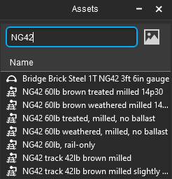 |
|
In the Assets Palette Left Click on the required item in the list. When selected the asset will be highlighted with a light grey background. |
|
Notes:
A Left Click on an asset in the Assets Palette filtered list will automatically activate the Placement Tool so the next Left Click will place that asset in your Trainz World. |
|
|
|
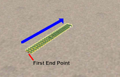 |
|
Move the mouse in the direction you want to lay the spline or track. The spline will follow the mouse wherever you move it.
|
When you start adding a spline to a route it will always be placed at the height of the terrain regardless of the Tool Options Palette Height setting. |
|
If there is a % value in the Grade setting then the spline will be laid down with a slope using that grade value starting from the terrain height at the first endpoint. If you don't want a grade and want each endpoint placed at the terrain height then delete any value (including 0%) stored in the Grade setting. |
|
Spine Laying Tips
Placement: Move a Spline Object
|
|
|
|
|
|
|
| Warning: |
|
To move a spline object DO NOT click on it with the Placement Tool as this will just add a junction |
|
| Steps: To move a spline segment |
|
In the Tools Palette Left Click on either the Free Move Tool (or press the S key) or the Fine Adjustment Tool (or press the D key) |
|
Select ( Left Click ) on the spline segment to be moved. To select multiple spline segments use Shift + Left Click on each segment |
|
Left Click and Drag the segment(s) in the required direction
|
Note: always drag on a segment not on an endpoint otherwise only the endpoint will be moved |
|
| For more information see the sections Free Move: Spline Objects or Fine Adjustment: Spline Objects |
|
|
|
|
Placement: Delete a Spline Object
|
|
|
|
|
|
|
To delete a spline object (or any object) that has just been added by the Placement Tool and is still highlighted, choose one of the following:-
Options: |
|
press the Delete key, OR |
|
open its Context Menu ( Left Click on its icon or press the T key) and select the option Delete |
|
If the object is not highlighted then you must first switch to either the Free Move Tool or the Fine Adjustment Tool, select the object and then choose one of the above options |
|
|
Placement: Add a Spline Junction
|
|
|
|
|
|
|
|
A junction is formed when three spline segments are joined at an endpoint. Junctions can be formed using non identical but compatible spline objects, such as different types of track splines. |
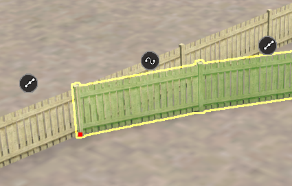 |
| Steps: To add a junction to a spline object:- |
|
Select the spline object to be used for the junction. The easiest method is hold down the Alt key and Left Click on an existing spline object that you want to use. This will also select the Placement Tool in Step 2 below so you can skip to Step 3 |
|
In the Tools Palette select the Placement Tool |
|
Left Click on the spline at the spot where the junction is to be created. This can be on an existing endpoint or between two endpoints where a new endpoint will be inserted |
|
All spline junctions will be shown with a red dot ( ). The only exception is for procedural track junctions where a red dot indicates a poorly formed junction while a ). The only exception is for procedural track junctions where a red dot indicates a poorly formed junction while a  black dot indicates a correctly formed junction. See Add a Track Junction below for more details black dot indicates a correctly formed junction. See Add a Track Junction below for more details |
|
|
move the mouse pointer out from the junction to where the next endpoint of the spline branch will be placed and Left Click |
|
|
|
Notes: Incompatible Splines
If, when forming a join or a junction between two splines, the message Incompatible Spline appears in the top right corner of the screen, then you are attempting to join two splines that are not compatible with each other. The join or junction between the splines will NOT be created. |
|
Placement: Separate Splines
|
|
|
|
|
|
|
| Steps: To remove a junction or a join between splines but keep all the spline segments:- |
|
open the endpoint Context Menu by a Left Click on its Context Icon  or by pressing the T key or by pressing the T key |
|
select the Separate Splines menu option. This will separate ALL the spline segments that meet at that endpoint without deleting any of the segments
|
If you have a segment or segments selected (highlighted) when you click the Separate Splines menu option then ALL the selected spline segments will be separated at their endpoints |
|
|
|
|
|
A spline junction or join can also be removed by deleting any spline segment that connects to its endpoint |
|
A junction endpoint can be moved by using the Free Move Tool or the Fine Adjustment Tool |
|
|
|
Placement: Add a Track Junction
|
|
|
|
|
|
|
|
A track junction is formed using track splines in the same way as described above but track junctions have additional features |
|
Using Procedural Tracks
If the track object used is a Procedural Track and the junction is formed with another Procedural Track then the junction endpoint dot will be coloured:- |
|
RED (as shown above) if the junction exceeds the maximum allowed values for a procedural junction. This will not stop the junction from working but it will not display the special features only found in Procedural Tracks, OR |
 |
BLACK if the junction is within the maximum allowed values for a procedural junction and it will display all the Procedural Track special features |
| A procedural track junction can be changed from red to black by adjusting the height and/or position (depending on the exact cause of the problem) of the junction endpoint and the endpoints on either side of the junction. See the Wiki Page How to Use Procedural Track for more details |
| A junction between two non-procedural tracks and between a procedural track and a non-procedural track will always have a red endpoint dot |
|
Placement: Set a Spline Height
|
|
|
|
|
|
|
|
If the Tool Options Palette and the Info Palette are not visible on the screen then refer to Notes: Palettes at the top of this document. |
|
Get the Height of a Spline Object
|
You can copy the height of a spline segment into the Tool Options Palette Height setting. Once it has been copied it can be applied to any other object. Choose one of the following:- |
| Options: |
|
Use the Eyedropper to copy the height (and gradient) of a spline segment
| Steps: To copy the Height of a spline segment:- |
|
hold down the Alt key and move the mouse tool pointer onto the spline segment |
|
while holding down the Alt key Left Click on the spline segment |
|
|
|
If the segment has a slope then the height at the point clicked with the eyedropper will be copied into the Height setting and the spline gradient will be copied into the Grade setting. |
|
This will also select the clicked object in the Assets Palette and it will become the next object added by a Left Click in your Trainz World |
|
|
|
| |
OR |
|
Use the Height setting drop down menu
| Steps: To copy the Height of the currently active (just placed) spline segment:- |
|
in the Tool Options Palette Right Click inside the Height setting box |
|
Select the Get Height from Selection option |
|
|
If the spline segment has a slope then the height at its midpoint will be used |
|
|
|
Set the Height of a Spline Object
To set the height of a selected spline segment (including track) or endpoint, choose one of the following:-
Options: |
|
If the selected spline segment has a Grade setting then Options and will adjust the height of each endpoint so that the heights will change but the grade will remain the same. Option will set both endpoints to the entered height and the grade will be removed |
|
|
Left Click in the Tool Options Palette Height setting and enter a new value (or keep the existing value) then press the Enter key, OR |
|
in the Tool Options Palette Left Click inside the Height setting and enter a new value (or keep the existing value) then Right Click in the setting box and select the Set Height to Selection option, OR |
|
from the objects Context Menu ( Left Click on the objects Context Icon or press the T key) select the Apply Height option, OR |
|
in the Info Palette enter a value in the objects Pos: z: (height) setting or Left Click and Drag Up or Down on the double arrowheads to its right. This can be used to set the height to cm accuracy (see The Info Palette below). |
|
All heights are relative to where an object is placed. Heights are not absolute. If a spline is placed 1 metre above the surface, for example, and is then moved along a slope it will always keep its height the same 1 metre above the surface at every point of the slope |
|
|
Placement: Set a Spline Gradient
|
|
|
|
|
|
|
|
If the Tool Options Palette and the Info Palette are not visible on the screen then refer to Notes: Palettes at the top of this document. |
|
|
Notes:
|
| |
The Grade is defined as vertical rise divided by horizontal distance converted to a percentage figure. So a grade of 100% (the maximum allowed) would mean a gradient formed by both measurements having the same value (e.g. a rise of 50m over a distance of 50m). A vertical slope (a cliff) would have an infinite grade (cliff height divided by 0) which is currently impossible in Surveyor. |
|
Get the Grade of a Spline Object
|
You can copy the grade of a spline segment into the Tool Options Palette Grade setting. Once it has been copied it can be applied to any other object. Choose one of the following:-
Options: |
|
Use the Eyedropper to copy the grade of any spline segment
| Steps: To copy the Grade of a spline segment:- |
|
hold down the Alt key and move the mouse tool pointer onto the spline segment |
|
while holding down the Alt key Left Click on the spline segment |
|
|
This will also change the asset selected in the Assets Palette to the object clicked and it will become the next object added by a Left Click with the Placement Tool |
|
| This will also copy the height of the segment at the point it was clicked into the Height setting |
|
| |
OR |
|
Use the Grade setting drop down menu
| Steps: To copy the Grade of the currently active (just placed) spline segment:- |
|
in the Tool Options Palette Right Click inside the Grade setting box |
|
Select the Get Grade from Selection option |
|
|
Set the Grade of a Spline Object
To set the gradient of a selected spline segment (including track) after it has been laid by the Placement Tool, choose one of the following:-
Options: |
|
in the Tool Options Palette Left Click inside the Grade setting and enter a new value (or keep the existing value) then press the Enter key. This works even if the Grade icon is not coloured Gold . OR |
|
select the Apply Grade to this Spline Endpoint option from the Context Menu for the segment endpoint (not the segment context icon) - Left Click on the endpoint Context Icon to apply the existing grade value. The endpoint that has been selected will be the starting point of the grade. |
|
You can lay a spline object without any applied gradient so that it will follow the existing terrain height. Simply delete its Grade value so it resets to the default - character |
|
|
Adding Spline Segments at a Set Gradient
To set and use the gradient of a spline object (including track) before it has been laid by the Placement Tool so that all the spline segments will be added with the set gradient in place, until it is changed or cancelled, then:-
Steps: To lay a spline sequence with a preset gradient:- |
|
in the Assets Palette Left Click on the spline asset to be added |
|
Left Click in the Tool Options Palette Grade setting and enter a new value (or keep the existing value) then press the Enter key. This works even if the Grade icon is not coloured Gold |
|
Left Click in the Surveyor World and draw out each spline segment as normal. Each segment will have the height of its second endpoint increased (or reduced for a negative grade) by an amount controlled by the Grade setting |
|
You can cancel or change the gradient at any time. The change will only affect any selected spline segment and any additional segments that are added after the change. Simply delete its Grade value so it resets to the default - or enter a new value |
|
|
Placement: Set Track Condition and Superelevation
|
|
|
|
|
|
|
|
The Track Condition sets the "smoothness" of the ride over a track segment. The default is 50% which is Average |
|
The Track Superelevation sets the height difference (as a angle) between the inner and outer rail lines on a curve |
|
Track Condition and Superelevation are only available for Track Splines |
Track Condition
|
If the Tool Options Palette is not visible on the screen then refer to Notes: Palettes at the top of this document. |
|
There are three different methods available for setting the track condition of a track segment.
|
The Tool Options Palette has a Condition setting that only applies to track spline segments. This can be set for a segment that has just been added and is still highlighted. |
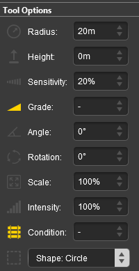 |
| Condition |
this applies to Track Spline objects and sets the track condition (or "ride comfort") for each segment |
| Range: |
1% (terrible track condition) to
50% (average track condition - the default setting) to
100% (perfect track condition)
|
|
|
| Steps: To set Track Condition:- |
|
Enter a value from 1 to 100 in the Tool Options Palette Condition setting |
|
Press the Enter key |
|
| There will be no visible change to the track appearance, not even for a 1% setting, as this change would have to be built into the track mesh. Instead when a consist moves over the track there will be a visible change in its rocking or swaying motion. |
|
|
A second method of setting the Track Condition of a newly placed track segment is to use its Track Segment Context Menu. |
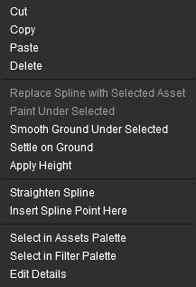 |
| Steps: To set the Track Condition of a newly placed track segment:- |
|
Left Click on the  Track Segment Context Icon to open its menu Track Segment Context Icon to open its menu |
|
Left Click on the Edit Details option at the bottom of the list |
|
Enter a track condition as a % value where it shows Default. The description on the right will change to show the effect of the new value
 |
|
Click Save Changes to set the new value and exit or Cancel to cancel the new value and exit |
|
|
|
A third method of setting the Track Condition is to use the Placement Tool to place an invisible track "bump" object on a track segment. |
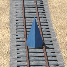
The "Track Bump" Object |
|
Track Superelevation
| The Track Superelevation can only be set through the Track Endpoint Context Menu. You can have a different value set for each endpoint that will reflect the changes that can take place around a curve. For more information on how to calculate and use Superelevation see the Trainz Wiki Page How to Use Superelevation |
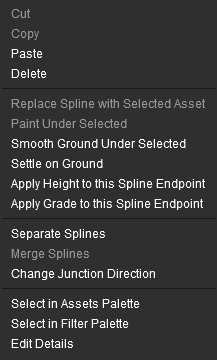 |
| Steps: To set the Superelevation for an endpoint of a newly placed track segment:- |
|
Left Click on the  Track Spline Endpoint Context Icon to open its menu Track Spline Endpoint Context Icon to open its menu |
|
Left Click on the Edit Details option at the bottom of the list |
|
Enter a Superelevation Degree as an angle (in degrees) - this is the superelevation angle at this vertex (endpoint) per degree of curvature where 0 = none |
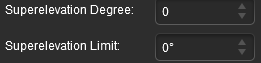 |
The Superelevation Angle is calculated using the radius of the curve, the maximum track speed and the track gauge.
See the Trainz Wiki Page How to Use Superelevation for the formula |
|
|
Enter a Superelevation Limit as an angle (in degrees) - this is the maximum allowed superelevation angle at this vertex (endpoint) |
|
Click Save Changes to set the new values and exit or Cancel to cancel the new values and exit |
| Repeat the above steps for each endpoint |
|
|
|
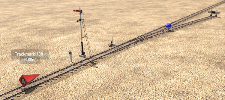
Typical Track Objects
Track marks, speed signs, signals (visible and invisible), switches, buffer stops |
Placement: Add a Track Object
|
|
|
|
|
|
|
|
Track Objects (e.g. signals, speed signs, switches, etc), both visible and invisible, can only be attached to track splines. |
|
Notes:
| Visible examples of track objects include:- |
|
Signals, speed signs, end buffers, switches |
| Invisible examples of track objects include:- |
|
Trackmarks, triggers, direction and priority markers. Plus invisible trackside objects such as signals, switches and speed signs |
|
|
|
|
If the Filter Palette and Assets Palette are not visible on the screen then refer to Notes: Palettes at the top of this document. |
|
| Steps: To add a Track Object the first step is to identify the exact asset you want to add. |
In the Filter Palette choose one of the following:-
|
In the Filter Palette the Track Objects icon will be shown in blue when it is selected and the name Track Objects will appear in the drop down box below the icons. For more information about the Filter Palette see the Trainz Wiki Page How to Use the Surveyor 2.0 Palettes - Filter Palette |
|
The Assets Palette display is controlled by the selections made in the Filter Palette . Selecting Scenery Objects in the Filter Palette will produce a list of all the installed Track Objects in the Assets Palette . For more information about the Assets Palette see the Trainz Wiki Page How to Use the Surveyor 2.0 Palettes - Assets Palette |
|
|
In the Assets Palette you have the option to narrow down the filtered list. Type the assets name or part of the name into the Search box. For example if you have selected Track Objects and want to find track objects named "speed board 50", then type "speedboard50" (UPPER/lower case and spaces between words do not matter).
This will list all the Track Objects containing variations of the texts "speed" + "board" + "50" in their names or descriptions as shown in the image below. |
|
The final step is to place the selected object into the route. |
Placement: Name a Track Object
|
|
|
|
|
|
|
|
Once a Track Object (e.g. a signal) has been placed it can be named using the Info Palette |
|
| Steps: To name (or rename) a selected Track Object:- |
KNOWN BUG
The method for naming (or renaming) a Track object is the same as it is for all other objects (see Setting an Objects Name). The difference is a "bug" that affects how changes to object names are handled. If you change the name of a Track Object the change will not be saved unless something else in the route is also changed. This bug only applies to Track Objects and not to scenery or spline objects (including track). An additional step, Step: 4 below, has been added as a "workaround" until this bug is fixed |
| Note: This must be performed immediately after the object has been placed while it is still highlighted (selected). If the object is not highlighted then select it with the Free Move Tool or the Fine Adjustment Tool. |
|
In the Info Palette Left Click inside the Name: text entry box |
|
If the Name: text entry box is greyed out and cannot be selected then the layer containing the object is locked. Use the Layers Palette to unlock the layer (see The Layers Palette), reselect the object and try again |
|
|
Enter or edit the name |
|
Press the Enter key |
|
Move a non-track object (e.g. a tree) before saving. If you have already edited something else in the route but not yet saved then this step will not be necessary |
|
|
Placement: Move a Track Object
|
|
|
|
|
|
|
|
Once a Track Object (e.g. a signal) has been placed it can be moved using the Placement Tool |
| Step: To move a Track Object using the Placement Tool:- |
|
Left Click and Drag the Anchor Point (the small yellow dot in the middle of the track as shown in the image above) to any position along the track or to another track.
|
You can also move the object by dragging the object itself and not its Anchor Point. However, it will lose its fixed distance, both vertical and horizontal, from the centre of the track. You will then have to open its Context Menu and select the Reattach to Track option to restore it to the correct distance from the track centre |
|
|
Placement: Delete a Track Object
|
|
|
|
|
|
|
To delete a track object (or any object) that has just been added by the Placement Tool and is still highlighted, choose one of the following:-
| Options: |
|
press the Delete key, OR |
|
open its Context Menu ( Left Click on its icon or press the T key) and select the option Delete |
|
If the object is not highlighted then you must first switch to either the Free Move Tool or the Fine Adjustment Tool, select the object and then choose one of the above options |
|
|
|
Placement: Set the Height of a Track Object
|
|
|
|
|
|
|
|
An object that has just been added to a route using the Placement Tool can have its height adjusted immediately after placement |
|
or it can be adjusted at a later time using the Free Move Tool or the Fine Adjustment Tool |
|
If the Tool Options Palette or the Info Palette are not visible on the screen then refer to Notes: Palettes at the top of this document. |
|
Get the Height of a Track Object
|
You can copy the height of a selected track object (e.g. a signal) into the Tool Options Palette Height setting while the Placement Tool is still active. Once it has been copied it can be applied to any other object.
| Steps: To copy the height of any selected track object into the Height setting:- |
|
In the Tool Options Palette Right Click in the Height setting |
|
select the Get Height from Selection option |
|
| |
| You can check the height of any selected object or endpoint using the Info Palette . The height is the last value in the Pos: (Position) data set. |
|
|
|
Set the Height of a Track Object
|
In Surveyor 2.0 track objects can be given a height that will place them above (or below) the track. To set the height of a selected track mesh object, choose one of the following:- |
| Options: |
|
in the Tool Options Palette Height setting, enter a value followed by the Enter key OR |
|
in the Tool Options Palette Height setting, enter a value then Right Click and select Set Height to Selection OR |
|
from the objects Context Menu select the Apply Height option to apply an existing height setting, OR |
|
in the Info Palette enter a value in the objects Pos: z: (height) setting or Left Click and Drag Up or Down on the double arrowheads to its right. This can be used to set the height to cm accuracy (see The Info Palette below). |
|
All heights are relative to the track where an object is placed. Heights are not absolute. If an object is placed 1 metre above the track, for example, and is then moved along a sloped track it will always keep its height the same 1 metre above the track at every point |
|
|
Placement: Set the Trigger Radius of a Track Object
|
|
|
|
|
|
|
|
Certain track objects have a Trigger Radius that sets how close a consist must approach the object to trigger its action |
|
The Trigger Radius of an object can be adjusted by the Placement Tool immediately after it has been placed on a track |
Track objects that have a Trigger Radius include:-
|
Track marks such as Track Markers, Priority Markers and Direction Markers |
|
Track Triggers |
|
Whistle Signs |
|
|
It is a good idea to adjust the trigger radius of these objects so that they do not overlap a track junction |
|
|
| The current Trigger Radius of these objects is shown by the size of the "wings" (Red or Green depending on the type of object) attached to the object and, in some cases, a distance value below the name of the object. Both of these options are shown in the image below. |
|
|
|
|
|
|
|
|
Track Mesh Object Context Menu Options |
|
Once a track mesh object has been placed you can open its Context Menu ( Left Click on its icon or press the T key) to access a range of options and functions. The following Track Object specific options will appear, along with other more general options, in the objects Context Menu.
|
| Rotate Trackside |
swaps the position of the object to the other side of the track or reverses its direction. With some Track Objects (e.g. Track Marks) the direction it is facing or pointing is not important |
|
| Change Junction Direction |
if the object is a track switch or junction then its switch direction will be reversed |
|
| Reattach to Track |
if the object has been moved away from the track then it will be reset to its correct position on the track. This option will be greyed out if the object is already attached to the track |
|
| See Free Move: Track Object Context Menu for the full list of Context Menu options for Track Objects. |
|
Placement: Rolling Stock Objects
|
|
|
|
|
|
|
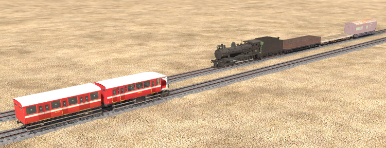
Typical Rolling Stock Objects
Locomotives, wagons, passenger cars |
Placement: Add a Rolling Stock Object
|
|
|
|
|
|
|
|
Rolling Stock Objects (e.g. locomotives, passenger cars and wagons) can only be attached to track splines. |
|
If the Filter Palette and Assets Palette are not visible on the screen then refer to Notes: Palettes at the top of this document. |
|
| Steps: To add a Rolling Stock Object the first step is to identify the exact asset you want to add. |
In the Filter Palette choose one of the following:-
|
In the Filter Palette the Trains icon will be shown in blue when it is selected and the name Trains will appear in the drop down box below the icons. For more information about the Filter Palette see the Trainz Wiki Page How to Use the Surveyor 2.0 Palettes - Filter Palette |
|
The Assets Palette display is controlled by the selections made in the Filter Palette . Selecting Scenery Objects in the Filter Palette will produce a list of all the installed Rolling Stock Objects in the Assets Palette . For more information about the Assets Palette see the Trainz Wiki Page How to Use the Surveyor 2.0 Palettes - Assets Palette |
|
|
In the Assets Palette you have the option to narrow down the filtered list. Type the assets name or part of the name into the Search box. For example if you have selected Trains and want to find rolling stock with "NG42" in their names, then type "NG42" (UPPER/lower case does not matter).
This will list all the Rolling Stock containing the text "NG42" in their names or descriptions. |
|
The final step is to place the selected object into the route. |
Placement: Load a Rolling Stock Object
|
|
|
|
|
|
|
|
Many rolling stock objects can carry products to be loaded and unloaded at industry objects |
|
Rolling stock objects can be preloaded with products when the Session starts |
|
Passenger rolling stock objects can carry passengers who will board and leave at specific industry objects (station platforms) |
Placement: Move a Rolling Stock Object
|
|
|
|
|
|
|
|
Once a Rolling Stock Object (e.g. a wagon) has been placed it can be moved using the Placement Tool |
|
Rolling Stock Objects are always attached to a track segment. They can be moved along the track or to a different track but they cannot be moved to a position that is to the left, right, above or below the track |
|
| Step: To move a Rolling Stock Object using the Placement Tool:- |
|
Left Click and Drag the Anchor Point (the small yellow dot attached to the object) to any position along the track or to another track. It can also be coupled to a consist and then decoupled by dragging the same Anchor Point. |
|
Placement: Delete a Rolling Stock Object
|
|
|
|
|
|
|
To delete a rolling stock object (or any object) that has just been added by the Placement Tool and is still highlighted, choose one of the following:-
Options: |
|
press the Delete key, OR |
|
open its Context Menu ( Left Click on its icon or press the T key) and select the option Delete |
|
If the object is not highlighted then you must first switch to either the Free Move Tool or the Fine Adjustment Tool, select the object and then choose one of the above options |
|
|
|
|
|
|
|
|
|
|
Rolling Stock Object Context Menu Options |
|
Once a rolling stock object has been placed you can open its Context Menu ( Left Click on its icon or press the T key) to access a range of options and functions. The following Rolling Stock Object specific options will appear, along with other more general options, in the objects Context Menu.
|
| Rotate Vehicle |
rotates (reverses) the facing direction of a selected rolling stock object. If more than one object has been selected then they will all have their directions reversed but they will remain in the same order |
| Change Consist Heading |
reverses the consist heading as indicated by the directions of the red and green arrows above the start and end of the consist |
| Rotate Consist Heading |
the entire consist is reversed, both in the order of the vehicles and the direction they face |
| Merge into Single Train |
when two or more separate rolling stock assets have been selected they will be coupled into a single consist. See Coupling Rolling Stock Objects for more details |
| Save to Consist Asset... |
saves the selected rolling stock objects as a new consist asset in the Assets Palette |
See Rolling Stock Object Context Menu for the full list of Context Menu options for Rolling Stock Objects. |
|
 |
Keyboard Shortcut: R |
|
|
The Eyedropper Tool identifies and selects objects in your Trainz World |
|
Various function of this tool use the Tool Options Palette Filter Palette and the Assets Palette . If these palettes are not visible on the screen when required then refer to Notes: Palettes at the top of this document. |
|
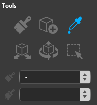 |
| Tool Targets The Eyedropper Tool has no Target options so it has no drop down menu list |
|
|
| Tool Actions The Eyedropper Tool has no Action options so it has no drop down menu list |
|
|
From the Eyedropper Tool
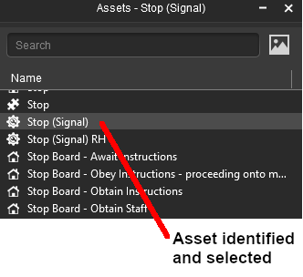 |
| Steps: To use the Eyedropper Tool:- |
|
In the Tools Palette select the Eyedropper Tool or press the R key |
|
move the pointer, which will look like an Eyedropper, over any object to reveal its name in a ToolTip which will appear below the pointer |
|
Optional: hold the eyedropper over any object for a few seconds to reveal more information such as its <kuid> code |
|
Optional: Left Click on the object to identify it in the Assets Palette It will be highlighted in light grey  |
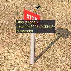 |
This will also switch control to the Placement Tool so the next Left Click in your Trainz World will add the selected asset to your layout. See Notes: below |
|
|
|
|
|
Notes:
|
| Using the Eyedropper Tool to select an object (Step 4 above) will also copy some of that objects properties into the Tool Options Palette . These would include:- |
|
Scale and Rotation for a ground texture |
|
Grade for a spline object (including track) |
| Adding the selected object to your layout will add it with those properties set. So, for example, if a spline object was selected then its Grade setting will be copied into the Tool Options Palette and that setting will be used when the spline is added to the layout |
|
From the Brush, Placement, Free Move, Fine Adjustment, Marquee Tools
|
You can access the Eyedropper while using any of the other tools in the Tools Palette |
| Steps: To access the Eyedropper from the other tools:- |
|
hold down the Alt key. The Eyedropper Tool will be temporarily selected in the Tools Palette |
|
move the Eyedropper onto an object to identify it as described above. The name and <kuid> of the object will appear in the pointer tooltip. If you release the Alt key without selecting an object then you will be returned to your originally selected tool in the Tools Palette |
|
while holding down the Alt key Left Click on the object to select it in the Assets Palette and copy some of its properties into the Tool Options Palette
|
If you change your mind you can Left Click on another object if you are still holding down the Alt key. If you have already released the Alt key then hold it down again to select another object |
|
|
after a Left Click on the selected object release the Alt key. The Placement Tool will be selected in the Tools Palette . This means that the next Left Click in your Trainz World will add the selected asset to your layout |
|
|
Sometimes (or often) a scene will be too crowded with different scenery objects to be able to use the Eyedropper Tool to easily select a single object. In these cases additional options are available to help "remove the clutter". |
|
If the Filter Palette and Assets Palette are not visible on the screen then refer to Notes: Palettes at the top of this document. |
|
These actions will affect the display and selection of objects in your Trainz World
|
Filter Actions |
|
| Filter Disabled |
this action disables the Filter Palette so that it has no filtering effect on the Assets Palette which will then display All (Installed) Content including those assets that are Obsolete or Disabled. Its main use is in the Bulk Replace Assets Tool (available in Trainz Plus only) but it can also be used to temporarily switch off the filters without having to delete them |
|
| Filter List |
this action is the default setting for the Filter Palette and displays, in both the Filter Palette and the Assets Palette , all the installed assets that match any search entered using the Filter Selection Options (the Asset Type icons and the Drop Down List of asset types, search filters and picklists). It has no effect on the operation of the tools in the Tools Palette or on the objects displayed on the screen in your Trainz World |
|
| Filter Selection |
this action will restrict the tools in the Tools Palette to those objects that are in the Assets Palette filtered list. Objects that are not in the filtered list will still be visible in your Trainz World but cannot be selected |
|
| Filter Visibility |
this action will hide all objects in your Trainz World that are not in the Assets Palette filtered list which also means that they cannot be selected. The only exceptions are Ground Textures and Effect Layers which will be visible but, unless they are also in the filtered list, cannot selected. |
|
|
|
As an example the following images show the progressive application of the Filter Actions.
 |
Keyboard Shortcut: S |
|
|
The Free Move Tool moves objects around your Trainz World |
|
Various function of this tool use the Tool Options Palette Info Palette Filter Palette and the Assets Palette . If these palettes are not visible on the screen when required then refer to Notes: Palettes at the top of this document. |
|
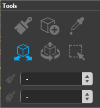 |
| Tool Targets The Free Move Tool has no Target options so it has no drop down menu list |
|
This tool is ideal for making large horizontal movements of objects |
|
Multiple objects (of different types) can be selected for mass moves and other operations |
|
| Tool Actions The Free Move Tool has no Action options so it has no drop down menu list |
|
The Free Move Tool is used for selecting and editing the following objects in a route:- |
|
|
| Free Move Alternatives |
| In addition to the Free Move Tool the position and/or height of objects can be changed by choosing one of the following:- |
| Options: |
|
using the Fine Adjustment Tool OR |
|
editing its x: y: z: values in The Info Palette OR |
|
selecting the Apply Height option in its Context Menu |
|
Free Move: Selecting an Object
|
|
|
|
|
|
|
|
The Free Move Tool can be used to select individual objects and multiple objects. The multiple objects can be of different types (e.g. spline objects and scenery objects) and in different layers |
| Steps: To select single and multiple objects with the Free Move Tool:- |
|
In the Tools Palette Left Click on the Free Move Tool or press the S key |
|
In the Surveyor screen Left Click on the object to be selected, or the first object if multiple objects are to be selected |
|
To select additional objects, hold down the Shift key and Left Click on each object to be added to the selection. The additional objects do not have to be the same type or in the same layer |
|
|
Double Left Click on an object to add it and all nearby identical objects into a single selection.
|
for a spline object all the segments up to the next junction (in both directions) will be selected |
|
for a rolling stock object all the rolling stock objects in that consist will be selected |
|
|
|
Notes:
|
|
To remove an object from the selection Left Click on it again if it is the only selected object or Shift + Left Click if it is one of several selected objects.
To remove ALL objects from a selection, Left Click on a Ground Texture or press the Ctrl + D keys |
|
When you select an object its Context Icon will appear attached to the object. Left Click on its icon or press the T key to open its Context Menu. If more than one object is selected then the Context Icon will be attached to the last object selected |
|
|
|
Selecting Objects From a Crowded Scene
Sometimes the object you want to select is part of a crowded scene or is overlapped by other objects, such as splines, and this can make it difficult to select. In these situations the best solution is to use the Filter Palette and Assets Palette to narrow the selection to a single object or to a set of objects.
See Narrowing the Search for more details |
|
Free Move: Naming an Object
|
|
|
|
|
|
|
|
Objects can be given names to help identify them with the Find Tool |
|
Some objects must be given unique names for display and session operations |
|
If the Info Palette is not visible on the screen then refer to Notes: Palettes at the top of this document. |
|
|
| Steps: To name (or rename) an object:- |
|
In the Info Palette Left Click inside the Name: text entry box |
|
If the Name: text entry box is greyed out and cannot be selected then the layer containing the object is locked. Use the Layers Palette to unlock the layer (see The Layers Palette), reselect the object and try again |
|
|
Enter or edit the name |
|
Press the Enter key |
|
KNOWN BUG: Changes to the name of a Track Object will not save unless something else in the route is also edited. The following additional step is a workaround when renaming Track Objects |
|
If renaming a track object then move a non-track object (e.g. a tree) before saving. If you have already edited something else in the route but not yet saved then this step will not be necessary |
|
|
|
If more than one object has been selected then only the last selected object, the one with the Context Icon, will be named. |
|
Free Move: Changing an Objects Layer
|
|
|
|
|
|
|
|
Layers are an essential feature of Trainz for managing different objects in Surveyor. Layers can be:- |
|
|
locked to prevent the accidental deletion, movement or alteration of the objects they contain |
|
hidden to remove their objects from view so that other nearby objects can be manipulated |
| Layers can also be used in Driver to hide and reveal objects during gameplay. |
|
|
More information on creating, editing and using Layers can be found on the Trainz Wiki Page at:-
|
|
|
|
If the Info Palette is not visible on the screen then refer to Notes: Palettes at the top of this document.
|
|
| An object will be added to a layer when it is placed into the Trainz World by the Placement Tool and the Scrapbook. Once it has been placed it can be moved to a different layer. |
|
| Steps: To move a placed object to another layer:- |
|
select the object ( Left Click on the object) or several objects ( Shift + Left Click on each object) to be moved to another layer. If multiple objects are selected then they do not have to be of the same type or in the same starting layer. Note: The layer(s) containing the object(s) must NOT be locked |
|
In the Info Palette Left Click on the Layer arrowhead icon (circled in red in the image left). This will open up the layer controls for the last selected object |
|
the drop down menu box labelled Layer shows the currently assigned layer for that object. If multiple objects from different layers have been selected then no layer name will be shown. Left Click on the Up/Down arrows to open the list of all available layers. |
|
select the destination layer from the list. The object(s) will then be moved to the selected layer - you will be given a warning if the move has failed (usually because an objects layer is locked) |
|
Also see:-
|
|
|
|
|
CAUTION: Take Care when assigning objects to layers |
|
Placing an object in the Route Layer Group will save it in the Route and it will appear in every Session based on that Route |
|
Placing an object in the Session Layer Group will save it in the Session and it will only appear in the currently loaded Session |
|
|
Notes:
The contents of the Ground Height Layer, Ground Texture Layer and the Effect Layers cannot be moved to other layers. Objects in the Route Layers Group and Session Layers Group cannot be moved into these layers |
|
Free Move: Scenery Mesh Objects
|
|
|
|
|
|
|
|
Individual "non-spline" scenery objects that are not attached to track are often referred to in Trainz terminology as Scenery Mesh Objects. |
|
If the Tool Options Palette and Info Palette are not visible on the screen then refer to Notes: Palettes at the top of this document.
|
|
Free Move: Move a Scenery Mesh Object
|
|
|
|
|
|
|
Free Move: Set the Height of a Scenery Mesh Object
|
|
|
|
|
|
|
Get the Height of a Scenery Mesh Object
|
You can copy the height of a selected scenery mesh object (e.g. a house) into the Tool Options Palette Height setting. Once it has been copied it can be applied to any other object. |
| |
| Steps: To copy the height of any selected object into the Height setting:- |
|
In the Tool Options Palette Right Click inside the Height setting |
|
select the Get Height from Selection option |
|
| |
| You can check the height of any selected object or endpoint using the Info Palette . The height is the last value in the Pos: (Position) data set. |
|
|
|
Set the Height of a Scenery Mesh Object
To set the height of a selected scenery mesh object, choose one of the following:-
Options: |
|
in the Tool Options Palette Left Click inside the Height setting and enter a new value (or keep the existing value) then press the Enter key. This works even if the Height icon is not coloured Gold . OR |
|
in the Tool Options Palette Left Click inside the Height setting and enter a new value (or keep the existing value) then Right Click in the setting box and select the Set Height to Selection option, OR |
|
select the Apply Height setting from the objects Context Menu ( Left Click on the objects Context Icon or press the T key) to apply an existing height value, OR |
|
in the Info Palette enter a value in the objects z: (height) setting or Left Click and Drag Up or Down on the double arrowheads to its right. This can be used to set the height to cm accuracy (see The Info Palette below). |
|
|
Notes:
|
|
All heights are relative to where an object is placed. Heights are not absolute. If a spline is placed 1 metre above the surface, for example, and is then moved along a slope it will always keep its height the same 1 metre above the surface at every point of the slope |
|
If multiple objects have been selected then the height of the context object, the one with the Context Icon, will have its height set to the new value. |
|
All other selected objects will have their heights adjusted to maintain their height relative to that object. For example: If another selected object is 2m below the context object then its adjusted height will always remain 2m below the context object |
|
|
Free Move: Configure an Industry Object
|
|
|
|
|
|
|
|
Some scenery mesh objects have been designed as Industry Objects that can produce and/or consume products |
|
These objects can be preset to process specific products and quantities when a Session starts |
| A selected scenery mesh object, or a group of selected scenery mesh objects, will have a Context Icon that opens a Context Menu. Left Click on its icon or press the T key. The icon design will vary between object types. |
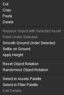 |
|
Scenery Mesh Object Context Menu Options
|
|
| Cut |
remove the selected object or objects from the route and move them into the Scrapbook |
|
| Copy |
copy the selected object or objects and place them into the Scrapbook |
|
| Paste |
paste the contents of the current Scrapbook at the cursor (focus) point
|
When pasted from a scrapbook the objects will be surrounded by a Marquee Selection Area that, depending on the settings in the Scrapbook Filters, may add to or replace all other objects, splines, textures, ground terrain and effect layers in that area |
|
|
| Delete |
delete the selected objects. It has the same effect as pressing the Delete key |
|
| Replace Object with Selected Asset |
the selected object will be replaced with the asset currently selected in the Assets Palette . If no object has been selected in the Assets Palette or it is the wrong type (e.g. a scenery spline instead of a mesh object) then this option will be greyed out |
|
| Paint Under Selected |
the texture selected in the Assets Palette will be painted under the selected objects. The Tool Options Palette brush settings ( Radius and Sensitivity ) will control how the texture is applied. If no ground texture has been selected in the Assets Palette then this option will be greyed out |
|
| Smooth Ground Under Selected |
smooths the height of the ground under the selected object to match the set height of the object. The size of the area affected will depend on which has the greater value: the width of the object OR the Tool Options Palette Radius setting. If multiple objects at different heights have been selected then the ground height will be set to match, as far as possible, the heights of each object |
|
| Settle on Ground |
sets the height of the objects to match the height of the terrain beneath them ("drops them back to earth") |
|
| Apply Height |
sets the height of the selected object to the value in the Tool Options Palette Height setting. Where multiple objects have been selected the context object, the one with the Context Icon, will have its height set to the Height value and the other selected objects will have their heights adjusted up or down by the same amount |
|
| Reset Object Rotation |
resets the rotation angle of the selected objects to their default values |
|
| Randomise Object Rotation |
applies a random rotation angle to each selected object around its vertical axis |
|
| Select in Assets Palette |
sets the Filter Palette to All Content and highlights the selected object in the Assets Palette |
|
| Select in Filter Palette |
sets the Filter Palette to All Content and highlights the selected object in the Filter Palette |
|
| Edit Details |
opens the Properties window of the selected object. Note: to enter or edit an objects name property use the Info Palette |
|
|
|
|
Track Objects (signals, switches, speed signs, markers, etc) are always attached to an existing track |
|
In Surveyor 2.0 they can be moved left, right, above and below the track |
Free Move: Move a Track Object
|
|
|
|
|
|
|
|
Track objects can be dragged to new positions along the track, beside the track or to a different track |
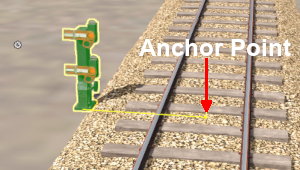 |
| Steps: To move a Track Object along the track using the Free Move Tool:- |
|
In the Tools Palette select the Free Move Tool or press the S key |
|
Left Click and Drag the objects Anchor Point (the small yellow dot in the middle of the track as shown in the image left) to any position along the track or to another track.
|
You can also move the object by dragging the object itself and not its Anchor Point. However, it will lose its fixed distance, both vertical and horizontal, from the centre of the track. You will then have to open its Context Menu and select the Reattach to Track option to restore it to the correct height and distance from the track centre |
|
|
|
| Situations where it is useful to be able to move a track object away from the track include:- |
|
placing Track Marks and Triggers above (see the next section) or beside the track so that they are not hidden by consists parked on top of them |
|
repositioning switches, signals, track signs closer to or further away from the track - particularly useful if the track object was originally created for a different gauge track |
|
Free Move: Set the Height of a Track Object
|
|
|
|
|
|
|
|
Track objects can be raised above and lowered below the track level. |
|
If the Info Palette and Tool Options Palette are not visible on the screen then refer to Notes: Palettes at the top of this document.
|
|
Get the Height of a Track Object
|
You can copy the height of a selected track mesh object (e.g. a signal) into the Tool Options Palette Height setting. Once it has been copied it can be applied to any other object. |
| |
| Steps: To copy the height of any selected object into the Height setting:- |
|
Right Click in the Height setting in the Tool Options Palette |
|
select the Get Height from Selection option |
|
|
Set the Height of a Track Object
| A situation where it might be useful to raise a signal above the track level would be to place it higher up on the wall of a cutting |
|
Free Move: Set the Trigger Radius of a Track Object
|
|
|
|
|
|
|
|
Certain track objects have have a Trigger Radius that sets how close a consist must approach the object to trigger its action |
|
Track objects that have a Trigger Radius include:- |
|
|
Track marks such as Track Markers, Priority Markers and Direction Markers |
|
Track Triggers |
|
Whistle Signs |
|
|
It is a good idea to adjust the trigger radius of these objects so that they do not overlap a track junction |
|
|
| The current Trigger Radius of these objects is shown by the size of the "wings" (Red or Green depending on the type of object) attached to the object and, in some cases, a distance value below the name of the object. Both of these options are shown in the image below. |
|
|
|
|
|
|
|
A selected track mesh object, or a group of selected track mesh objects, will have a Context Icon that opens a Context Menu. The icon design will vary between object types.
To open a selected track objects Context Menuchoose one of the following:-
| Options: |
|
Left Click the Context Icon  OR OR |
|
Press the T key |
|
|
|
Track objects can also be rotated to the opposite side of the track to face the opposite direction.
For some track objects this will make no difference but for others it will have an affect on their operation - for example:- |
|
|
signals and trackside signs (e.g. speed, whistle and stop signs) |
|
track direction markers and directional triggers |
|
| if rotated these track objects will now only affect trains approaching from the direction that is opposite to the way that they originally faced. |
|
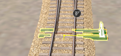 |
| Steps: To rotate a track object:- |
|
Open the track objects Context Menu ( Left Click on its icon or press the T key) |
|
Select the option Rotate Trackside |
| Rotating a track object does not change its distance from the track or its height.
|
|
|
Free Move: Spline Objects (Including Track)
|
|
|
|
|
|
|
|
Scenery splines and track splines are defined by their endpoints. Splines are usually added to a route as a series of segments joined at the endpoints. |
|
If the Tool Options Palette and Info Palette are not visible on the screen then refer to Notes: Palettes at the top of this document.
|
|
Free Move: Spline Troubleshooting Tip
|
|
|
|
|
|
|
|
Quickly Locate Broken Splines and Tracks |
| |
To quickly check for broken links in a spline or track Double Left Click on a segment. All the correctly joined segments upto the next junction or last endpoint (in both directions) will be highlighted. The highlighting will stop at a broken join (which is technically a "last" endpoint) |
|
Free Move: Moving Splines
|
|
|
|
|
|
|
| Moving a spline can involve moving one of the following:- |
| Options: |
|
moving an endpoint, OR |
|
moving a segment, OR |
|
moving multiple segments including the entire length of the spline (between junctions) |
|
Free Move: Move a Spline Endpoint
Free Move: Move a Spline Segment or Multiple Segments
Splines are frequently made of multiple segments joined together. You can easily move a spline by moving its segments, individually or as a group.
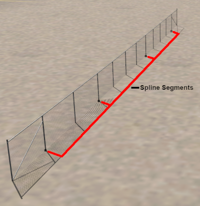 |
|
Not all splines have endpoints at each end. As shown in the image on the left, some splines will have an "endcap" that is attached to the start of the first segment and to the end of the last segment, although not all splines with endcaps will have one at each end. The use of an endcap is a purely cosmetic effect - to give the spline a more distinctive appearance. |
|
|
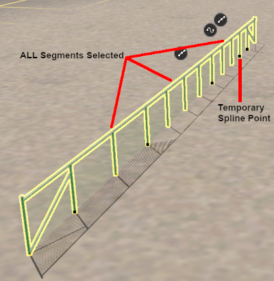 |
| IF you are going to select and move more than one spline segment, then:- |
|
hold the Shift key down and individually Left Click between the endpoints on each additional segment. The last segment that you Left Click on will have a temporary endpoint (placed at the spot you clicked) and the Context Icons added. |
|
To select ALL the segments in a spline, Double Left Click on a segment
|
This will select all the segments upto the next junction or the final endpoint (in both directions) |
|
The segment that you double-clicked will have the temporary endpoint (placed at the spot you clicked) and Context Icons added |
|
|
|
|
To remove individual spline segments from the selection Shift + Left Click on each segment to be removed. |
|
To remove ALL the segments from a selection, Double Left Click on any highlighted segment OR Left Click anywhere outside the selected segments. |
|
|
|
|
Left Click and Drag the selected segment(s) in any horizontal direction.
| If you had selected:- |
|
only a single spline segment then only that segment will be moved and the adjacent segments that were not selected will have their shapes (but not their endpoints) adjusted |
|
multiple spline segments then those segments will be moved and the adjacent segments that were not selected will also have their shapes adjusted |
|
the entire spline then ALL the segments and endpoints will be moved |
|
Free Move: Join Splines
|
|
|
|
|
|
|
|
Existing splines can be joined together at endpoints to create a longer spline or to create a junction between the two splines |
|
Joins and junctions can be formed using non identical but compatible spline objects, such as different types of track splines. |
|
The Free Move Tool can be used to form a join or a junction between existing but separated splines and endpoints by dragging the terminating endpoint of one spline onto an endpoint of the other spline. If the Target endpoint is:-
|
at the end of the second spline then a join will be made that will increase the total length of the spline |
|
between two of the segments of the second spline then the join will form a new junction between the splines |
| The two splines must be identical or compatible. See Notes: Incompatible Splines below. |
|
|
Free Move: Separate Splines
|
|
|
|
|
|
|
| Steps: To remove a junction or a join between splines but keep all the spline segments:- |
|
use the Free Move Tool to select ( Left Click on) the junction or join endpoint |
|
open the endpoint Context Menu by a Left Click on its Context Icon or by pressing the T key |
|
select the Separate Splines menu option. This will separate ALL the spline segments that meet at that endpoint without deleting any of the segments
|
If you have a segment or segments selected (highlighted) when you click the Separate Splines menu option then ALL the selected spline segments will be separated at their endpoints |
|
|
|
|
|
A spline junction or join can also be removed by deleting any spline segment that connects to its endpoint |
|
A junction endpoint can be moved by using the Free Move Tool or the Fine Adjustment Tool |
|
|
|
Free Move: Add a Track Junction
|
|
|
|
|
|
|
|
A track junction is formed using track splines in the same way as described above but track junctions have additional features |
|
Using Procedural Tracks
If the track object used is a Procedural Track and the junction is formed with another Procedural Track then the junction endpoint dot will be coloured:- |
|
RED (as shown above) if the junction exceeds the maximum allowed values for a procedural junction. This will not stop the junction from working but it will not display the special features only found in Procedural Tracks, OR |
|
BLACK if the junction is within the maximum allowed values for a procedural junction and it will display all the Procedural Track special features |
| A procedural track junction can be changed from red to black by adjusting the height and/or position (depending on the exact cause of the problem) of the junction endpoint and the endpoints on either side of the junction. See the Wiki Page How to Use Procedural Track for more details |
| A junction between two non-procedural tracks and between a procedural track and a non-procedural track will always have a red endpoint dot |
|
Free Move: Set a Spline Height
|
|
|
|
|
|
|
Get the Height of a Spline Object
|
You can copy the height of a spline segment or endpoint into the Tool Options Palette Height setting. Once it has been copied it can be applied to any other object. Choose one of the following:- |
| Options: |
|
Use the Eyedropper to copy the height of a spline segment
| Steps: To copy the Height of a spline segment (but not an endpoint):- |
|
hold down the Alt key and move the mouse tool pointer onto the spline segment |
|
while holding down the Alt key Left Click on the spline segment |
|
|
|
When the eyedropper is active spline endpoints will not be visible and cannot be selected |
|
If the segment has a slope then the height at the point clicked will be copied into the Height setting |
|
This will also select the clicked object in the Assets Palette and it will become the next object added by a Left Click with the Placement Tool in your Trainz World |
|
|
|
| |
OR |
|
Use the Height setting drop down menu
| Steps: To copy the Height of a spline segment or one of its endpoints:- |
|
Left Click on the spline segment or endpoint |
|
in the Tool Options Palette Right Click inside the Height setting box |
|
Select the Get Height from Selection option |
|
|
If the spline segment has a slope then the height at its midpoint will be used |
|
|
|
Set the Height of a Spline Object
To set the height of a selected spline (including track) or endpoint, choose one of the following:-
Options: |
|
If the selected spline segments have a Grade setting then Options and will adjust the height of each segment endpoint so that the heights will change but the grade will remain the same. Option will set all the endpoints to the entered height and the grade will be removed |
|
|
Left Click in the Tool Options Palette Height setting and enter a new value (or keep the existing value) then press the Enter key. This works even if the Height icon is not coloured Gold . OR |
|
in the Tool Options Palette Left Click inside the Height setting and enter a new value (or keep the existing value) then Right Click in the setting box and select the Set Height to Selection option, OR |
|
select the Apply Height option from the objects Context Menu ( Left Click on the objects Context Icon or press the T key) to apply an existing height value, OR |
|
in the Info Palette enter a value in the objects z: (height) setting or Left Click and Drag Up or Down on the double arrowheads to its right. This can be used to set the height to cm accuracy (see The Info Palette below). |
|
All heights are relative to where an object is placed. Heights are not absolute. If a spline object is placed 1 metre above the surface, for example, and is then moved along a slope it will always keep its height the same 1 metre above the surface at every point of the slope |
|
|
| Steps: To set the heights of multiple spline segments to the value stored in the Tool Options Palette Height setting:- |
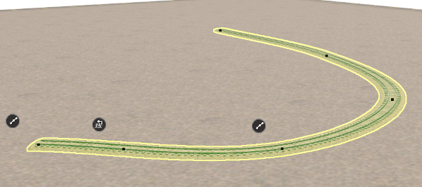 |
|
Select the spline segments using:-
|
Shift + Left Click to select individual segments, OR |
|
Double Left Click to select all the segments up to the next junction (in both directions). |
|
|
Select one of the options , , or described above |
|
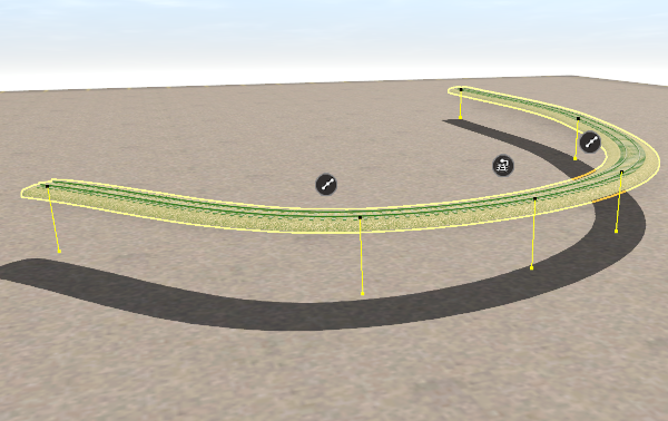 |
ALL the selected spline segments and their endpoints will be set to the specified height. |
|
Free Move: Set a Spline Gradient
|
|
|
|
|
|
|
|
Notes:
|
| |
The Grade is defined as vertical rise divided by horizontal distance converted to a percentage figure. So a grade of 100% (the maximum allowed) would mean a gradient formed by both measurements having the same value (e.g. a rise of 50m over a distance of 50m). A vertical slope (a cliff) would have an infinite grade (cliff height divided by 0) which is currently impossible in Surveyor. |
|
Get the Grade of a Spline Object
|
You can copy the current Grade of any spline segment into the Tool Options Palette Grade setting. Once it has been copied it can be applied to any other object that has a Grade setting. Choose one of the following:-
Options: |
|
Use the Eyedropper
| Steps: To copy the Grade of a spline segment (but not an endpoint):- |
|
hold down the Alt key and move the mouse tool pointer onto the spline segment |
|
while holding down the Alt key Left Click on the spline segment |
|
|
When the eyedropper is active spline endpoints will not be visible and cannot be selected. This option will also change the asset selected in the Assets Palette to the object clicked and it will become the next object added by a Left Click with the Placement Tool |
|
The height at the point clicked will also be copied into the Height setting |
| |
OR |
|
Use the Grade setting drop down menu
| Steps: To copy the Grade of a spline segment or one of its endpoints:- |
|
Left Click on the spline segment or endpoint |
|
in the Tool Options Palette Right Click inside the Grade setting box |
|
Select the Get Grade from Selection option |
|
|
Set the Grade of a Spline Object
To set the gradient of a selected spline segment (including track), choose one of the following:-
Options: |
|
in the Tool Options Palette Left Click inside the Grade setting and enter a new value (or keep the existing value) then press the Enter key. This works even if the Grade icon is not coloured Gold . OR |
|
select the Apply Grade to this Spline Endpoint option from the Context Menu for the segment endpoint (not the segment context icon) - Left Click on the endpoint Context Icon to apply the existing grade value. The endpoint that has been selected will be the starting point of the grade. |
|
Free Move: Set Track Condition and Superelevation
|
|
|
|
|
|
|
|
The Track Condition sets the "smoothness" of the ride over a track segment. The default is 50% which is Average |
|
The Track Superelevation sets the height difference (as a angle) between the inner and outer rail lines on a curve |
|
Track Condition and Superelevation are only available for Track Splines |
Track Condition
|
If the Tool Options Palette is not visible on the screen then refer to Notes: Palettes at the top of this document. |
|
There are three different methods available for setting the track condition of a track segment.
|
The Tool Options Palette has a Condition setting that only applies to track spline segments. |
|
A second method of setting the Track Condition of a selected track segment is to use its Track Segment Context Menu. |
|
| Steps: To set the Track Condition of a single selected track segment:- |
|
Left Click on the Track Segment Context Icon to open its menu |
|
Left Click on the Edit Details option at the bottom of the list |
|
Enter a track condition as a % value where it shows Default. The description on the right will change to show the effect of the new value
|
|
Click Save Changes to set the new value and exit or Cancel to cancel the new value and exit |
|
|
Track Superelevation
| The Track Superelevation can only be set through the Track Endpoint Context Menu. You can have a different value set for each endpoint that will reflect the changes that can take place around a curve. For more information on how to calculate and use Superelevation see the Trainz Wiki Page How to Use Superelevation |
|
| Steps: To set the Superelevation for an endpoint of a newly placed track segment:- |
|
Left Click on the Track Spline Endpoint Context Icon to open its menu |
|
Left Click on the Edit Details option at the bottom of the list |
|
Enter a Superelevation Degree as an angle (in degrees) - this is the superelevation angle at this vertex (endpoint) per degree of curvature where 0 = none |
|
The Superelevation Angle is calculated using the radius of the curve, the maximum track speed and the track gauge.
See the Trainz Wiki Page How to Use Superelevation for the formula |
|
|
Enter a Superelevation Limit as an angle (in degrees) - this is the maximum allowed superelevation angle at this vertex (endpoint) |
|
Click Save Changes to set the new values and exit or Cancel to cancel the new values and exit |
| Repeat the above steps for each endpoint |
|
|
|
|
|
|
|
|
|
|
| A selected scenery spline object, or a group of selected scenery spline objects, will have Context Icons. The icon design will vary between object types and their position on the spline object. Each icon will open its own Context Menu. |
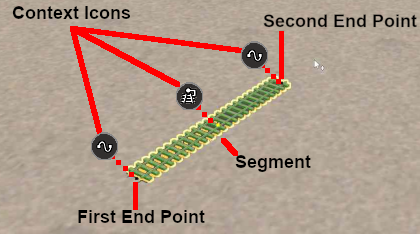 |
|
Notes:
|
| Splines have two different Context Icons that lead to two slightly different Context Menus. |
|
one context icon and menu for each endpoint |
|
one context icon and menu for the segment |
| If multiple segments have been selected then the last segment added to the selection will have the context icons. If all the segments were selected by a Double Left Click then the segment that was clicked will have the icons. |
|
|
|
To open a selected objects Context Menu choose one of the following:-
| Options: |
|
Left Click the Context Icon  OR OR |
|
Press the T key |
|
|
|
|
Notes: Using the T key with splines
|
|
If a spline segment has been selected then pressing the T key will open the Segment Context Menu and the Menu options you select or edit will apply to the whole segment or all selected segments |
| |
|
|
If a spline end point has been selected then pressing the T key will open the End Point Context Menu and the Menu options you select or edit will only apply to that particular endpoint |
|
|
| Spline Object Context Menus |
Endpoint Context Menu
|
Segment Context Menu
|
|
|
Spline Object Context Menu Options |
|
|
When copying/moving track segments into a scrapbook any track objects on the segments will be included in the scrapbook |
| Cut |
remove the selected segment or segments from the route and move them into the Scrapbook ( only) |
|
| Copy |
copy the selected segment or segments and place them into the Scrapbook ( only) |
|
| Paste |
paste the contents of the current Scrapbook at the cursor (focus) point
|
When pasted from a scrapbook the objects will be surrounded by a Marquee Selection Area that, depending on the settings in the Scrapbook Filters, may add to or replace all other objects, splines, textures, ground terrain and effect layers in that area |
|
|
| Delete |
delete the segment, segments or endpoint. It has the same effect as pressing the Delete key |
|
| Replace Spline with Selected Asset |
the highlighted spline will be replaced with the asset currently selected in the Assets Palette . If the asset selected in the Assets Palette is the wrong type (e.g. a mesh object instead of a scenery spline) then this option will be greyed out ( only) |
|
| Paint Under Selected |
the texture selected in the Assets Palette will be painted under the selected objects. The Tool Options Palette brush settings ( Radius and Sensitivity ) will control how the texture is applied. If no ground texture has been selected in the Assets Palette then this option will be greyed out ( only) |
|
Objects have a minimum brush size that represents the smallest area that can be painted beneath them using the Paint Under Selected option. This minimum area will vary in size between objects but it will be rectangular even for circular objects. If the Tool Options Palette brush Radius is set to a smaller size then the brush Radius will be ignored and the objects minimum brush size will be used instead. |
|
|
| Smooth Ground Under Selected |
smooths the height of the ground under the selected spline to match its set height. If multiple spline segments have been selected then the ground under all the segments will be smoothed to their height. The size of the area affected will depend on which has the greater value: the width of the spline OR the Tool Options Palette Radius setting. Does not work for endpoints |
|
| Settle on Ground |
sets the height of the selected endpoint or segments to match the height of the terrain beneath them ("drops them back to earth"). When used on segments the spline will follow the height changes of the terrain |
|
| Apply Height to this Spline Endpoint |
sets the height of the selected endpoint to the value in the Tool Options Palette Height setting ( only) |
|
|
You can copy the Height from an existing spline endpoint into the Height setting of the Tool Options Palette . Once it has been copied it can be applied to any other object.
hold down the Alt key and Left Click on the spline endpoint to copy its Height value. That value can then be used to set the Height of other spline endpoints |
|
| Apply Height |
sets the height of the selected segment or segments to the value in the Tool Options Palette Height setting ( only) |
|
| Apply Grade to this Spline Endpoint |
you must first select a segment then click on one of its endpoint icons . This sets the height of the endpoint to give a Grade to the surrounding segments that matches the value in the Tool Options Palette Grade setting |
|
|
You can copy the Grade from an existing spline segment into the Grade setting of the Tool Options Palette . Once it has been copied it can be applied to any other object.
hold down the Alt key and Left Click on the spline segment to copy its Grade value. That value can then be used to set the Grade of other spline segments |
|
| Straighten Spline |
forces a straight line (as far as possible) between the endpoints of a single segment. This option will be  ticked if the segment has already been straightened in which case selecting this option will "un-straighten" the segment and remove the tick ( only) ticked if the segment has already been straightened in which case selecting this option will "un-straighten" the segment and remove the tick ( only) |
|
| Separate Splines |
breaks two spline segments into two separate (independent) splines at the selected endpoint
|
If multiple segments have been selected then this option will break ALL the selected segments into separate (independent) splines |
|
| Merge Splines |
removes the selected endpoint between two segments and merges the segments into one ( only). Two segments can also be merged by deleting a selected endpoint with the Delete key |
|
| Insert Spline Point Here |
splits the selected segment into two segments by adding a new endpoint at the point where the segment was clicked ( only) |
|
| Select in Assets Palette |
sets the Filter Palette to All Content and highlights the selected object in the Assets Palette |
|
| Select in Filter Palette |
sets the Filter Palette to All Content and highlights the selected object in the Filter Palette |
|
| Edit Details |
opens the Properties window of the selected spline object. This option is only available for Track splines. Note: to enter or edit an objects name property use the Info Palette |
|
|
Free Move: Rolling Stock Objects
|
|
|
|
|
|
|
|
Rolling Stock Objects (locomotives, wagons, etc) can only be moved along the track that they are attached to. If they are moved off the track then they will immediately "snap back" to the nearest track when they are released. |
|
If the Tool Options Palette and Info Palette are not visible on the screen then refer to Notes: Palettes at the top of this document.
|
|
Free Move: Load a Rolling Stock Object
|
|
|
|
|
|
|
|
Many rolling stock objects can carry products to be loaded and unloaded at industry objects |
|
Rolling stock objects can be preloaded with products when the Session starts |
|
Passenger rolling stock objects can carry passengers who will board and leave at specific industry objects (station platforms) |
Free Move: Move Rolling Stock Objects
|
|
|
|
|
|
|
Use the Free Move tool to move a selected rolling stock object along the track.
|
Rolling Stock Objects are always attached to a track segment. They can be moved along the track or to a different track but they cannot be moved to a position that is to the left, right, above or below the track |
|
| To move an entire consist of rolling stock objects, Double Left Click on any one of the objects in the consist to select them all and then move them as one object |
|
Free Move: Decouple Rolling Stock Objects
|
|
|
|
|
|
|
|
All decoupling operations between Rolling Stock Objects are performed using just a Left Click and Drag. |
| To decouple a rake of joined rolling stock objects from a consist (for example, the first or last 5 wagons), Shift + Left Click on each of the objects to be selected and then drag them away from the consist |
|
A rolling stock object or objects in the middle of a consist can also be decoupled. This will break the consist into 3 sections.
Free Move: Couple Rolling Stock Objects
|
|
|
|
|
|
|
|
All coupling operations between Rolling Stock Objects can be performed using just a Left Click and Drag or through the objects Context Menu. |
Options:
Using "Click and Drag"
Consider the following simple situation:-
Using the Context Menu
Using the same situation as above, the isolated guard van and the gondola wagon at the end of a consist are to be coupled together.
There are two possible outcomes depending on which object has the Context Icon
| Using a more complex example involving multiple objects from several different consists. The selected wagons shown below are to form a single consist based on the loco. |
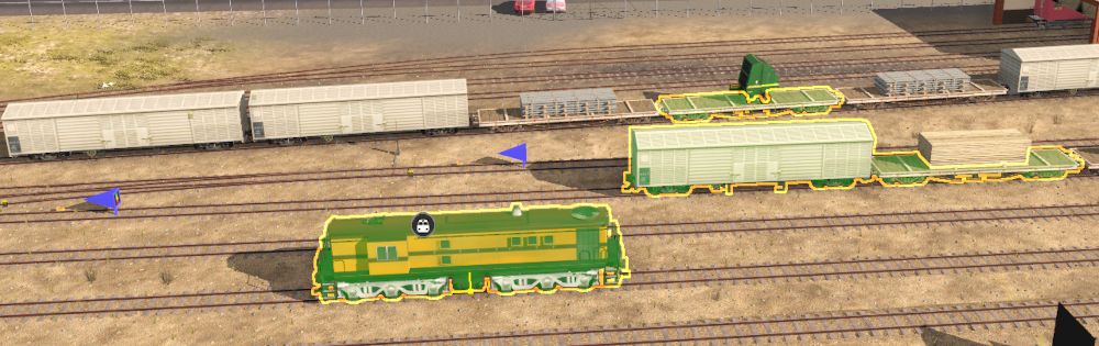 |
| The loco was the last object to be selected so it has the Context Icon. The Context Menu is opened and the option Merge into Single Train is selected with the result as shown below. |
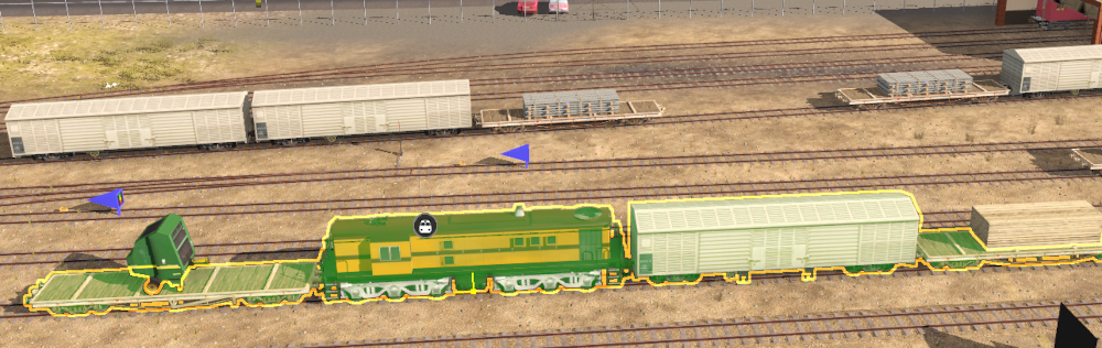 |
| The wagons and loco have been combined into a single consist but not necessarily in a useful order. Left Click and Drag the incorrectly placed vehicles to their correct positions. |
| A selected rolling stock object, or a group of selected rolling stock objects, will have a Context Icon that opens a Context Menu. The icon design will vary between object types. |
To open a selected rolling stock object's Context Menu choose one of the following:-
| Options: |
|
Left Click its Context Icon  OR OR |
|
Press the T key |
|
|
|
|
You cannot add rolling stock assets to a Scrapbook but you can create and save Consist Assets that have multiple rolling stock objects
| Steps: To create a Consist Asset:- |
|
select the consist - Double Left Click on the consist or Shift + Left Click on individual items |
|
open the consist Context Menu - Left Click on its icon or press the T key |
|
select the option Save to Consist Asset... |
|
enter a name and an optional description for your new Consist Asset and click the icon |
| The consist will appear as a Train Asset in the Assets Palette |
|
|
|
 |
Keyboard Shortcut: D |
|
|
The Fine Adjustment Tool makes 3D adjustments (XYZ position and rotations) to objects in your Trainz World |
|
Various function of this tool use the Tool Options Palette Info Palette Filter Palette and the Assets Palette . If these palettes are not visible on the screen when required then refer to Notes: Palettes at the top of this document. |
|
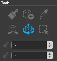 |
| Tool Targets The Fine Adjustment Tool has no Target options so it has no drop down menu list |
|
This tool is ideal for making small adjustments to objects - horizontally, vertically and rotations in 3D space |
|
Multiple objects (of different types) can be selected for mass adjustments and other operations |
|
| Tool Actions The Fine Adjustment Tool has no Action options so it has no drop down menu list |
|
The Fine Adjustment Tool is used for selecting and editing the following objects in a route:- |
|
|
| Fine Adjustment Alternatives |
| In addition to the Fine Adjustment Tool the position, orientation and/or height of objects can be changed by choosing one of the following:- |
| Options: |
|
using the Free Move Tool OR |
|
editing its x: y: z: position values and r: p: y: rotation values in The Info Palette OR |
|
selecting the Apply Height option in its Context Menu |
|
|
The most obvious feature of the Fine Adjustment Tool is the 3D Anchor Frame it adds to a selected object. The frame is made of 3 straight and 3 curved coloured lines plus a central dot, called Anchors |
|
The Anchors in the Fine Adjustment Tool are used to move and rotate a selected object, or a group of selected objects, through 3D space. |
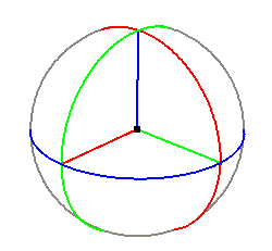 |
The Anchor controls are:-
| The Horizontal and Vertical Anchors |
| Red Green Blue |
move the object (forward/back or up/down) in the direction of the Anchor line |
| The Rotational Anchors |
| Red Green Blue |
rotate the object (clockwise and anti-clockwise) along the Anchor Arc Line centred around the Anchor Straight Line of the same colour |
|
Not all objects will have Red and/or Green rotational Anchors. Some objects will have no rotational anchors at all. |
|
|
| The Object Anchor |
| (black central dot) moves the object in any horizontal direction |
|
|
The orientation of the Red and Green horizontal anchor lines is based on the orientation of the object when it is placed in the scene, not on the compass directions |
|
|
| Steps: To use the Fine Adjustment Tool controls:- |
|
move the tool pointer onto an Anchor - its colour will change to yellow for Anchor lines or green for the Object Anchor |
|
Left Click and Drag the Object Anchor in any direction or move the pointer along the chosen Anchor Line in the required direction (e.g. up on the blue vertical Anchor or clockwise around the arc of the red rotational Anchor) |
|
|
| To achieve finer and more accurate control when moving anchors, choose one of the following:- |
| Options: |
|
zoom in closer to the anchor point, OR |
|
use the x: y: z: fine adjustment arrows in the Info Palette object Pos: controls. These arrows can be used to set the height and position to cm accuracy (see The Info Palette below), OR |
|
use the r: p: y: fine adjustment arrows in the Info Palette object Rot: controls. These arrows can be used to set the rotation to 1° accuracy (see The Info Palette below). |
|
Fine Adjustment: Selecting an Object
|
|
|
|
|
|
|
|
The Fine Adjustment Tool can be used to select individual objects and multiple objects. The multiple objects can be of different types (e.g. spline objects and scenery objects) and in different layers |
| Steps: To select single and multiple objects with the Fine Adjustment Tool:- |
|
In the Tools Palette Left Click on the [[image:S20_FineAdjustmentToolIcon.png|link=|20px] Fine Adjustment Tool] or press the D key |
|
In the Surveyor screen Left Click on the object to be selected, or the first object if multiple objects are to be selected |
|
To select additional objects, hold down the Shift key and Left Click on each object to be added to the selection. The additional objects do not have to be the same type or in the same layer |
|
|
Double Left Click on an object to add it and all nearby identical objects into a single selection.
|
for a spline object all the segments up to the next junction (in both directions) will be selected |
|
for a rolling stock object all the rolling stock objects in that consist will be selected |
|
|
|
Notes:
|
|
To remove an object from the selection Left Click on it again if it is the only selected object or Shift + Left Click if it is one of several selected objects.
To remove ALL objects from a selection, Left Click on a Ground Texture or press the Ctrl + D keys |
|
When you select an object its Context Icon will appear attached to the object. Left Click on its icon or press the T key to open its Context Menu. If more than one object is selected then the Context Icon will be attached to the last object selected |
|
|
|
Selecting Objects From a Crowded Scene
Sometimes the object you want to select is part of a crowded scene or is overlapped by other objects, such as splines, and this can make it difficult to select. In these situations the best solution is to use the Filter Palette and Assets Palette to narrow the selection to a single object or to a set of objects.
See Narrowing the Search for more details |
|
Fine Adjustment: Naming an Object
|
|
|
|
|
|
|
|
Objects can be given names to help identify them with the Find Tool |
|
Some objects must be given unique names for display and session operations |
|
If the Tool Options Palette and Info Palette are not visible on the screen then refer to Notes: Palettes at the top of this document.
|
|
|
| Steps: To name (or rename) an object:- |
|
In the Info Palette Left Click inside the Name: text entry box |
|
If the Name: text entry box is greyed out and cannot be selected then the layer containing the object is locked. Use the Layers Palette to unlock the layer (see The Layers Palette), reselect the object and try again |
|
|
Enter or edit the name |
|
Press the Enter key |
|
KNOWN BUG: Changes to the name of a Track Object will not save unless something else in the route is also edited. The following additional step is a workaround when renaming Track Objects |
|
If renaming a track object then move a non-track object (e.g. a tree) before saving. If you have already edited something else in the route but not yet saved then this step will not be necessary |
|
|
|
If more than one object has been selected then only the last selected object, the one with the Context Icon, will be named. |
|
Fine Adjustment: Changing an Objects Layer
|
|
|
|
|
|
|
|
All objects in the Trainz World are in layers. For scenery objects you can set and change the layers where they are placed |
|
Layers are an essential feature of Trainz for managing different objects in Surveyor. Layers can be:- |
|
|
locked to prevent the accidental deletion, movement or alteration of the objects they contain |
|
hidden to remove their objects from view so that other nearby objects can be manipulated |
| Layers can also be used in Driver to hide and reveal objects during gameplay. |
|
|
More information on creating, editing and using Layers can be found on the Trainz Wiki Page at:-
|
|
|
|
If the Info Palette is not visible on the screen then refer to Notes: Palettes at the top of this document |
|
| An object will be added to a layer when it is placed into the Trainz World by the Placement Tool and the Scrapbook. Once it has been placed it can be moved to a different layer. |
|
| Steps: To move a placed object to another layer:- |
|
select the object ( Left Click on the object) or several objects ( Shift + Left Click on each object) to be moved to another layer. If multiple objects are selected then they do not have to be of the same type or in the same starting layer. Note: The layer(s) containing the object(s) must NOT be locked |
|
in the Info Palette Left Click on the Layer arrowhead icon (circled in red in the image left). This will open up the layer controls for the last selected object |
|
the drop down menu box labelled Layer shows the currently assigned layer for that object. If multiple objects from different layers have been selected then no layer name will be shown. Left Click on the Up/Down arrows to open the list of all available layers. |
|
select the destination layer from the list. The object(s) will then be moved to the selected layer - you will be given a warning if the move has failed (usually because an objects layer is locked) |
|
Also see:-
|
|
|
|
|
CAUTION: Take Care when assigning objects to layers |
|
Placing an object in the Route Layer Group will save it in the Route and it will appear in every Session based on that Route |
|
Placing an object in the Session Layer Group will save it in the Session and it will only appear in the currently loaded Session |
|
|
Notes:
The contents of the Ground Height Layer, Ground Texture Layer and the Effect Layers cannot be moved to other layers. Objects in the Route Layers Group and Session Layers Group cannot be moved into these layers |
|
Fine Adjustment: Scenery Mesh Objects
|
|
|
|
|
|
|
|
Individual "non-spline" scenery objects that are not attached to track are often referred to in Trainz terminology as Scenery Mesh Objects. |
|
If the Tool Options Palette and Info Palette are not visible on the screen then refer to Notes: Palettes at the top of this document.
|
|
Fine Adjustment: Move a Scenery Mesh Object
|
|
|
|
|
|
|
| To move an object with the Fine Adjustment Tool choose one of the following:- |
| Options: |
|
Left Click and Drag anywhere on the selected object (except on an Anchor line) to move it freely in any horizontal direction |
|
OR |
|
Left Click and Drag on an Anchor line to move or rotate it in the direction of the line or arc |
| These operations can also be performed on a group of selected objects. The 3D Anchor Frame will be on the last object added to the group. |
|
Using the Anchors
Blue vertical Anchor movement
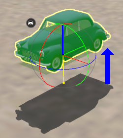 |
|
Green Anchor rotation
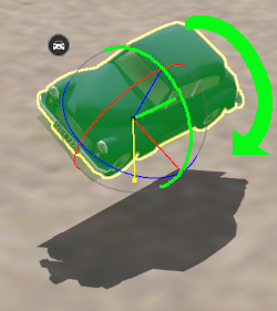 |
|
Red Anchor rotation
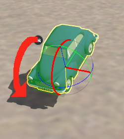 |
|
Blue Anchor rotation
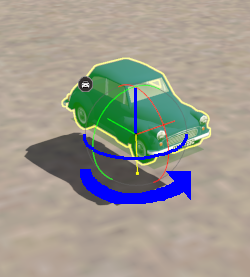 |
|
Notes:
|
|
Not all objects will have Red or Green Rotational Anchors. Some objects will have no rotational anchors at all. |
|
Objects can be restored to their original height and rotation settings by opening their Context Menu and choosing one of the following:-
| Options: |
|
Reset Object Rotation to cancel the rotation changes, OR |
|
Settle on Ground to cancel the height change |
|
|
The Randomise Object Rotation option in the Context Menu only affects rotations around the vertical axis - the Blue Rotational Anchor.
|
|
Fine Adjustment: Set the Height of a Scenery Mesh Object
|
|
|
|
|
|
|
|
Scenery Mesh objects can be raised above and lowered below the ground level. |
Get the Height of a Scenery Mesh Object
|
You can copy the height of a selected scenery mesh object (e.g. a house) into the Tool Options Palette Height setting. Once it has been copied it can be applied to any other object. |
| |
| Steps: To copy the height of any selected object into the Height setting:- |
|
in the Tool Options Palette Right Click inside the Height setting |
|
select the Get Height from Selection option |
|
| |
| You can check the height of any selected object or endpoint using the Info Palette . The height is the last value in the Pos: (Position) data set. |
|
|
|
Set the Height of a Scenery Mesh Object
To set the height of a selected scenery mesh object, choose one of the following:-
Options: |
|
Left Click and Drag Up/Down on the Blue vertical Anchor line. Movement is restricted to the length of the Anchor line only , OR |
|
in the Tool Options Palette Left Click inside the Height setting and enter a new value (or keep the existing value) then press the Enter key. This works even if the Height icon is not coloured Gold . OR |
|
in the Tool Options Palette Left Click inside the Height setting and enter a new value (or keep the existing value) then Right Click in the setting box and select the Set Height to Selection option, OR |
|
select the Apply Height option from the objects Context Menu ( Left Click on the objects Context Icon or press the T key) to apply an existing height value, OR |
 |
in the Info Palette enter a value in the objects z: (height) setting or Left Click and Drag Up or Down on the double arrowheads to its right. This can be used to set the height to cm accuracy (see The Info Palette below). |
|
|
Notes:
|
|
All heights are relative to where an object is placed. Heights are not absolute. If a spline is placed 1 metre above the surface, for example, and is then moved along a slope it will always keep its height the same 1 metre above the surface at every point of the slope |
|
If multiple objects have been selected then the height of the context object, the one with the Context Icon, will have its height set to the new value. |
|
All other selected objects will have their heights adjusted to maintain their height relative to that object. For example: If another selected object is 2m below the context object then its adjusted height will always remain 2m below the context object |
|
|
Fine Adjustment: Configure an Industry Object
|
|
|
|
|
|
|
|
Some scenery mesh objects have been designed as Industry Objects that can produce and/or consume products |
|
These objects can be preset to process specific products and quantities when a Session starts |
| A selected scenery mesh object, or a group of selected scenery mesh objects, will have a Context Icon that opens a Context Menu. Left Click on its icon or press the T key. The icon design will vary between object types. |
|
|
Scenery Mesh Object Context Menu Options
|
|
| Cut |
remove the selected object or objects from the route and move them into the Scrapbook |
|
| Copy |
copy the selected object or objects and place them into the Scrapbook |
|
| Paste |
paste the contents of the current Scrapbook at the cursor (focus) point
|
When pasted from a scrapbook the objects will be surrounded by a Marquee Selection Area that, depending on the settings in the Scrapbook Filters, may add to or replace all other objects, splines, textures, ground terrain and effect layers in that area |
|
|
| Delete |
delete the selected objects. It has the same effect as pressing the Delete key |
|
| Replace Object with Selected Asset |
the selected object will be replaced with the asset currently selected in the Assets Palette . If no object has been selected in the Assets Palette or it is the wrong type (e.g. a scenery spline instead of a mesh object) then this option will be greyed out |
|
| Paint Under Selected |
the texture selected in the Assets Palette will be painted under the selected objects. The Tool Options Palette brush settings ( Radius and Sensitivity ) will control how the texture is applied. If no ground texture has been selected in the Assets Palette then this option will be greyed out |
|
| Smooth Ground Under Selected |
smooths the height of the ground under the selected object to match the set height of the object. The size of the area affected will depend on which has the greater value: the width of the object OR the Tool Options Palette Radius setting. If multiple objects at different heights have been selected then the ground height will be set to match, as far as possible, the heights of each object |
|
| Settle on Ground |
sets the height of the objects to match the height of the terrain beneath them ("drops them back to earth") |
|
| Apply Height |
sets the height of the selected object to the value in the Tool Options Palette Height setting. Where multiple objects have been selected the context object, the one with the Context Icon, will have its height set to the Height value and the other selected objects will have their heights adjusted up or down by the same amount |
|
| Reset Object Rotation |
resets the rotation angle of the selected objects to their default values |
|
| Randomise Object Rotation |
applies a random rotation angle to each selected object around its vertical axis |
|
| Select in Assets Palette |
sets the Filter Palette to All Content and highlights the selected object in the Assets Palette |
|
| Select in Filter Palette |
sets the Filter Palette to All Content and highlights the selected object in the Filter Palette |
|
| Edit Details |
opens the Properties window of the selected object. Note: to enter or edit an objects name property use the Info Palette |
|
|
|
Fine Adjustment: Track Objects
|
|
|
|
|
|
|
|
Track Objects (signals, switches, speed signs, markers, etc) are always attached to an existing track |
|
In Surveyor 2.0 they can be moved left, right, above and below the track |
|
If the Tool Options Palette and Info Palette are not visible on the screen then refer to Notes: Palettes at the top of this document.
|
|
Fine Adjustment: Move a Track Object
|
|
|
|
|
|
|
|
Track objects can be dragged to new positions along and beside the track or to a different track |
| Situations where it is useful to be able to move a track object away from the track include:- |
|
placing Track Marks and Triggers above (see the next section) or beside the track so that they are not hidden by consists parked on top of them |
|
repositioning switches, signals, track signs closer to or further away from the track - particularly useful if the track object was originally created for a different gauge track |
|
Fine Adjustment: Set the Height of a Track Object
|
|
|
|
|
|
|
|
Track objects can be raised above and lowered below the track level. |
Get the Height of a Track Object
|
You can copy the height of a selected track mesh object (e.g. a signal) into the Tool Options Palette Height setting. Once it has been copied it can be applied to any other object. |
| |
| Steps: To copy the height of any selected object into the Height setting:- |
|
in the Tool Options Palette Right Click inside the Height setting |
|
select the Get Height from Selection option |
|
|
Set the Height of a Track Object
Fine Adjustment: Set the Trigger Radius of a Track Object
|
|
|
|
|
|
|
|
Certain track objects have a Trigger Radius that sets how close a consist must approach the object to trigger its action |
Track objects that have a Trigger Radius include:-
|
Track marks such as Track Markers, Priority Markers and Direction Markers |
|
Track Triggers |
|
Whistle Signs |
|
|
It is a good idea to adjust the trigger radius of these objects so that they do not overlap a track junction |
|
|
| The current Trigger Radius of these objects is shown by the size of the "wings" (Red or Green depending on the type of object) attached to the object and, in some cases, a distance value below the name of the object. Both of these options are shown in the image below. |
|
|
|
|
|
|
|
A selected track mesh object, or a group of selected track mesh objects, will have a Context Icon that opens a Context Menu. The icon design will vary between object types.
To open a selected track objects Context Menu choose one of the following:-
| Options: |
|
Left Click the Context Icon OR |
|
Press the T key |
|
|
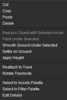 |
|
Track Object Context Menu Options |
|
|
Track objects can be copied/moved into a scrapbook by themselves but when pasted/painted they will appear without any track. They will be automatically added to a scrapbook by selecting and copying or cutting the track segments under the objects |
| Cut |
remove the selected object or objects from the route and move them into the Scrapbook |
|
| Copy |
copy the selected object or objects and place them into the Scrapbook |
|
| Paste |
paste the contents of the current Scrapbook at the cursor (focus) point
|
When pasted from a scrapbook the objects will be surrounded by a Marquee Selection Area that, depending on the settings in the Scrapbook Filters, may add to or replace all other objects, splines, textures, ground terrain and effect layers in that area |
|
|
| Delete |
delete the selected objects. It has the same effect as pressing the Delete key |
|
| Replace Object with Selected Asset |
the selected object will be replaced with the asset currently selected in the Assets Palette . If the asset selected in the Assets Palette is the wrong type (e.g. a scenery spline) then this option will be greyed out |
|
| Paint Under Selected |
the texture selected in the Assets Palette will be painted under the selected objects. The Tool Options Palette brush settings ( Radius and Sensitivity ) will control how the texture is applied. If no ground texture has been selected in the Assets Palette then this option will be greyed out. |
|
Objects have a minimum brush size that represents the smallest area that can be painted beneath them using the Paint Under Selected option. This minimum area will vary in size between objects but it will be rectangular even for circular objects. If the Tool Options Palette brush Radius is set to a smaller size then the brush Radius will be ignored and the objects minimum brush size will be used instead. |
|
|
| Smooth Ground Under Selected |
smooths the height of the ground under the selected object to match the set height of the object. For track objects the size of the area affected will depend on the Tool Options Palette Radius setting |
|
| Settle on Ground |
sets the height of the objects to match the height of the terrain beneath them ("drops them back to earth") |
|
| Apply Height |
sets the height of the selected object to the value in the Tool Options Palette Height setting. Where multiple objects have been selected the context object, the one with the Context Icon, will have its height set to the Height value and the other selected objects will have their heights adjusted up or down by the same amount |
|
| Reattach to Track |
if the object has been moved away from the track then it will be reset to its correct position on the track. This option will be greyed out if the object is already attached to the track |
|
| Rotate Trackside |
reverses the position of the object on the track to the other side and facing the opposite direction |
|
| Change Junction Direction |
if the object is a track switch then its switch direction will be reversed |
|
| Select in Assets Palette |
sets the Filter Palette to All Content and highlights the selected object in the Assets Palette |
|
| Select in Filter Palette |
sets the Filter Palette to All Content and highlights the selected object in the Filter Palette |
|
| Edit Details |
opens the Properties window of the selected rolling stock object. Note: to enter or edit an objects name property use the Info Palette |
|
|
|
|
Notes:
|
| |
Track objects can be restored to their original height and position (on the track) by opening their Context Menu and choosing one of the following:-
| Options: |
|
Reattach to Track to cancel the both the height and position changes, OR |
|
Settle on Ground to cancel the height change only |
|
|
Track objects can also be rotated to the opposite side of the track to face the opposite direction.
For some track objects this will make no difference but for others it will have an affect on their operation - for example:- |
|
signals and trackside signs (e.g. speed, whistle and stop signs) |
|
track direction markers and directional triggers |
| |
if rotated these track objects will now only affect trains approaching from the opposite direction to the direction that they originally faced. |
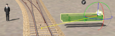 |
| Steps: To rotate a track object:- |
|
Open the track objects Context Menu ( Left Click on its icon or press the T key) |
|
Select the option Rotate Trackside |
| Rotating a track object does not change its distance from the track or its height.
|
|
|
Fine Adjustment: Spline Objects (Including Track)
|
|
|
|
|
|
|
|
Scenery splines and track splines are defined by their endpoints. Splines are usually added to a route as a series of segments joined at the endpoints. |
|
If the Tool Options Palette and Info Palette are not visible on the screen then refer to Notes: Palettes at the top of this document.
|
|
Fine Adjustment: Spline Troubleshooting Tip
|
|
|
|
|
|
|
|
Quickly Locate Broken Splines and Tracks |
| |
To quickly check for broken links in a spline or track Double Left Click on a segment. All the correctly joined segments upto the next junction or last endpoint (in both directions) will be highlighted. The highlighting will stop at a broken join (which is technically a "last" endpoint) |
|
Fine Adjustment: Moving Splines
|
|
|
|
|
|
|
| Moving a spline can involve moving one of the following:- |
| Options: |
|
moving an endpoint, OR |
|
moving a segment, OR |
|
moving multiple segments including the entire length of the spline (between junctions) |
|
Fine Adjustment: Move a Spline Endpoint
Fine Adjustment: Move a Spline Segment or Multiple Segments
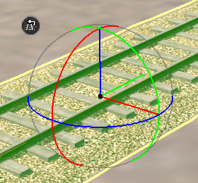 |
The 3D Anchor Frame shown is for a spline segment.
| Steps: To move spline segments:- |
|
Select the Fine Adjustment Tool |
|
Select, Left Click on, the spline segment to be moved.
|
To select:-
|
more than one segment - Shift + Left Click on each segment |
|
ALL the segments - Double Left Click on a segment. This will the select segments in both directions from the segment clicked upto the next junction or the final endpoint |
|
|
|
Left Click and Drag one of the following:- |
| |
| Options: |
|
an Anchor Line to move the segment or segments in that specific direction, OR |
|
anywhere in a segment to move it in any direction in the horizontal plane |
|
|
|
|
To remove individual spline segments from the selection simply Shift + Left Click on each segment to be removed. |
|
To remove ALL the segments from a selection, Double Left Click on any highlighted segment OR Left Click anywhere outside the selected segments. |
|
|
|
a Blue line height change and a Red Anchor rotation can be cancelled at any time (even after saving and reloading the route) by selecting the Settle on Ground option from the segments Context Menu |
|
a Blue Anchor rotation can be straightened at any time (even after saving and reloading the route) by selecting the Straighten Spline option from the segments Context Menu but this will not return the endpoints to their original positions
|
|
|
Fine Adjustment: Rotate Multiple Spline Segments
| You can rotate multiple selected spline segments around any of its 3D Anchor Frames. |
| Steps: To Rotate Multple Splne Segments |
|
Select the Fine Adjustment Tool |
|
Double Left Click on the spline segment that will be the centre of the rotation or contains the endpoint that will be the pivot of the rotation. The entire spline will be selected but the Anchor Frames will only be on the segment that was clicked
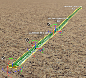 |
|
Left Click and Drag on the Blue rotational anchor line of the Anchor Frame that will be used as the pivot or centre of rotation
| The selected Anchor Frame can be at one of the two terminal endpoints for the entire spline or at any location on one of the spline segments. In either case the selected Anchor Frame will be the pivot point for the rotation |
 |
 |
|
|
Fine Adjustment: Join Splines
|
|
|
|
|
|
|
|
Existing splines can be joined together at endpoints to create a longer spline or to create a junction between the two splines |
|
Joins and junctions can be formed using non identical but compatible spline objects, such as different types of track splines. |
|
The Fine Adjustment Tool can be used to form a join or a junction between existing but separated splines and endpoints by dragging the terminating endpoint of one spline onto an endpoint of the other spline. If the Target endpoint is:-
|
at the end of the second spline then a join will be made that will increase the total length of the spline |
|
between two of the segments of the second spline then the join will form a new junction between the splines |
| The two splines must be identical or compatible. See Notes: Incompatible Splines below. |
|
|
Fine Adjustment: Separate Splines
|
|
|
|
|
|
|
| Steps: To remove a junction or a join between splines but keep all the spline segments:- |
|
use the Fine Adjustment Tool to select ( Left Click on) the junction or join endpoint |
|
open the endpoint Context Menu by a Left Click on its Context Icon or by pressing the T key |
|
select the Separate Splines menu option. This will separate ALL the spline segments that meet at that endpoint without deleting any of the segments
|
If you have a segment or segments selected (highlighted) when you click the Separate Splines menu option then ALL the selected spline segments will be separated at their endpoints |
|
|
|
|
|
A spline junction or join can also be removed by deleting any spline segment that connects to its endpoint |
|
A junction endpoint can be moved by using the Free Move Tool or the Fine Adjustment Tool |
|
|
|
Fine Adjustment: Add a Track Junction
|
|
|
|
|
|
|
|
A track junction is formed using track splines in the same way as described above but track junctions have additional features |
|
Using Procedural Tracks
If the track object used is a Procedural Track and the junction is formed with another Procedural Track then the junction endpoint dot will be coloured:- |
|
RED (as shown above) if the junction exceeds the maximum allowed values for a procedural junction. This will not stop the junction from working but it will not display the special features only found in Procedural Tracks, OR |
|
BLACK if the junction is within the maximum allowed values for a procedural junction and it will display all the Procedural Track special features |
| A procedural track junction can be changed from red to black by adjusting the height and/or position (depending on the exact cause of the problem) of the junction endpoint and the endpoints on either side of the junction. See the Wiki Page How to Use Procedural Track for more details |
| A junction between two non-procedural tracks and between a procedural track and a non-procedural track will always have a red endpoint dot |
|
Fine Adjustment: Set a Spline Height
|
|
|
|
|
|
|
Get the Height of a Spline Object
|
You can copy the height of a spline segment or endpoint into the Tool Options Palette Height setting. Once it has been copied it can be applied to any other object. Choose one of the following:- |
| Options: |
|
Use the Eyedropper to copy the height of a spline segment
| Steps: To copy the Height of a spline segment (but not an endpoint):- |
|
hold down the Alt key and move the mouse tool pointer onto the spline segment |
|
while holding down the Alt key Left Click on the spline segment |
|
|
|
When the eyedropper is active spline endpoints will not be visible and cannot be selected |
|
If the segment has a slope then the height at the point clicked will be copied into the Height setting |
|
This will also select the clicked object in the Assets Palette and it will become the next object added by a Left Click with the Placement Tool in your Trainz World |
|
|
|
| |
OR |
|
Use the Height setting drop down menu
| Steps: To copy the Height of a spline segment or one of its endpoints:- |
|
Left Click on the spline segment or endpoint |
|
in the Tool Options Palette Right Click inside the Height setting box |
|
Select the Get Height from Selection option |
|
|
If the spline segment has a slope then the height at its midpoint will be used |
|
|
|
Set the Height of a Spline Object
To set the height of a selected spline segment (including track) or endpoint using the Fine Adjustment Tool choose one of the following:-
Options: |
|
If the selected spline segments have a Grade setting then Options and will adjust the height of each segment endpoint so that the heights will change but the grade will remain the same. Option will set all the endpoints to the entered height and the grade will be removed |
|
|
Left Click and Drag Up or Down on the vertical Blue anchor line in the 3D Anchor Frame. OR |
|
in the Tool Options Palette Left Click inside the Height setting and enter a new value (or keep the existing value) then press the Enter key. This works even if the Height icon is not coloured Gold . OR |
|
in the Tool Options Palette Left Click inside the Height setting and enter a new value (or keep the existing value) then Right Click in the setting box and select the Set Height to Selection option, OR |
|
select the Apply Height option from the objects Context Menu ( Left Click on the objects Context Icon or press the T key) to apply an existing height value, OR |
|
in the Info Palette enter a value in the objects Pos: z: (height) setting or Left Click and Drag Up or Down on the double arrowheads to its right. This can be used to set the height to cm accuracy (see The Info Palette below). |
|
All heights are relative to where an object is placed. Heights are not absolute. If a spline is placed 1 metre above the surface, for example, and is then moved along a slope it will always keep its height the same 1 metre above the surface at every point of the slope |
|
|
| Steps: To set the heights of multiple spline segments to the value stored in the Tool Options Palette Height setting:- |
|
|
Select the spline segments using:-
|
Shift + Left Click to select individual segments, OR |
|
Double Left Click to select all the segments up to the next junction (in both directions). |
|
|
Select one of the options , , , or described above |
|
|
ALL the selected spline segments and their endpoints will be set to the specified height. |
|
Fine Adjustment: Set a Spline Gradient
|
|
|
|
|
|
|
|
Notes:
|
| |
The Grade is defined as vertical rise divided by horizontal distance converted to a percentage figure. So a grade of 100% (the maximum allowed) would mean a gradient formed by both measurements having the same value (e.g. a rise of 50m over a distance of 50m). A vertical slope (a cliff) would have an infinite grade (cliff height divided by 0) which is currently impossible in Surveyor. |
|
Get the Grade of a Spline Object
|
You can copy the current Grade of any spline segment into the Tool Options Palette Grade setting. Once it has been copied it can be applied to any other object that has a Grade setting. Choose one of the following:-
Options: |
|
Use the Eyedropper
| Steps: To copy the Grade of a spline segment (but not an endpoint):- |
|
hold down the Alt key and move the mouse tool pointer onto the spline segment |
|
while holding down the Alt key Left Click on the spline segment |
|
|
When the eyedropper is active spline endpoints will not be visible and cannot be selected. This option will also change the asset selected in the Assets Palette to the object clicked and it will become the next object added by a Left Click with the Placement Tool |
|
The height at the point clicked will also be copied into the Height setting |
| |
OR |
|
Use the Grade setting drop down menu
| Steps: To copy the Grade of a spline segment or one of its endpoints:- |
|
Left Click on the spline segment or endpoint |
|
in the Tool Options Palette Right Click inside the Grade setting box |
|
Select the Get Grade from Selection option |
|
|
Set the Grade of a Spline Object
Fine Adjustment: Set Track Condition and Superelevation
|
|
|
|
|
|
|
|
The Track Condition sets the "smoothness" of the ride over a track segment. The default is 50% which is Average |
|
The Track Superelevation sets the height difference (as a angle) between the inner and outer rail lines on a curve |
|
Track Condition and Superelevation are only available for Track Splines |
Track Condition
|
If the Tool Options Palette is not visible on the screen then refer to Notes: Palettes at the top of this document. |
|
There are three different methods available for setting the track condition of a track segment.
|
The Tool Options Palette has a Condition setting that only applies to track spline segments. |
|
A second method of setting the Track Condition of a selected track segment is to use its Track Segment Context Menu. |
|
| Steps: To set the Track Condition of a single selected track segment:- |
|
Left Click on the Track Segment Context Icon to open its menu |
|
Left Click on the Edit Details option at the bottom of the list |
|
Enter a track condition as a % value where it shows Default. The description on the right will change to show the effect of the new value
|
|
Click Save Changes to set the new value and exit or Cancel to cancel the new value and exit |
|
|
Track Superelevation
| The Track Superelevation can only be set through the Track Endpoint Context Menu. You can have a different value set for each endpoint that will reflect the changes that can take place around a curve. For more information on how to calculate and use Superelevation see the Trainz Wiki Page How to Use Superelevation |
|
| Steps: To set the Superelevation for an endpoint of a newly placed track segment:- |
|
Left Click on the Track Spline Endpoint Context Icon to open its menu |
|
Left Click on the Edit Details option at the bottom of the list |
|
Enter a Superelevation Degree as an angle (in degrees) - this is the superelevation angle at this vertex (endpoint) per degree of curvature where 0 = none |
|
The Superelevation Angle is calculated using the radius of the curve, the maximum track speed and the track gauge.
See the Trainz Wiki Page How to Use Superelevation for the formula |
|
|
Enter a Superelevation Limit as an angle (in degrees) - this is the maximum allowed superelevation angle at this vertex (endpoint) |
|
Click Save Changes to set the new values and exit or Cancel to cancel the new values and exit |
| Repeat the above steps for each endpoint |
|
|
|
|
|
|
|
|
|
|
| A selected scenery spline object, or a group of selected scenery spline objects, will have Context Icons. The icon design will vary between object types and their position on the spline object. Each icon will open its own Context Menu. |
|
|
Notes:
|
| Splines have two different Context Icons that lead to two slightly different Context Menus. |
|
one context icon and menu for each endpoint |
|
one context icon and menu for the segment |
| If multiple segments have been selected then the last segment added to the selection will have the context icons. If all the segments were selected by a Double Left Click then the segment that was clicked will have the icons. |
|
|
|
To open a selected objects Context Menu choose one of the following:-
| Options: |
|
Left Click the Context Icon OR |
|
Press the T key |
|
|
|
|
Notes: Using the T key with splines
|
|
If a spline segment has been selected then pressing the T key will open the Segment Context Menu and the Menu options you select or edit will apply to the whole segment or all selected segments |
| |
|
|
If a spline end point has been selected then pressing the T key will open the End Point Context Menu and the Menu options you select or edit will only apply to that particular endpoint |
|
|
| Spline Object Context Menus |
Endpoint Context Menu
|
Segment Context Menu
|
|
|
Spline Object Context Menu Options |
|
|
When copying/moving track segments into a scrapbook any track objects on the segments will be included in the scrapbook |
| Cut |
remove the selected segment or segments from the route and move them into the Scrapbook ( only) |
|
| Copy |
copy the selected segment or segments and place them into the Scrapbook ( only) |
|
| Paste |
paste the contents of the current Scrapbook at the cursor (focus) point
|
When pasted from a scrapbook the objects will be surrounded by a Marquee Selection Area that, depending on the settings in the Scrapbook Filters, may add to or replace all other objects, splines, textures, ground terrain and effect layers in that area |
|
|
| Delete |
delete the segment, segments or endpoint. It has the same effect as pressing the Delete key |
|
| Replace Spline with Selected Asset |
the highlighted spline will be replaced with the asset currently selected in the Assets Palette . If the asset selected in the Assets Palette is the wrong type (e.g. a mesh object instead of a scenery spline) then this option will be greyed out ( only) |
|
| Paint Under Selected |
the texture selected in the Assets Palette will be painted under the selected objects. The Tool Options Palette brush settings ( Radius and Sensitivity ) will control how the texture is applied. If no ground texture has been selected in the Assets Palette then this option will be greyed out ( only) |
|
Objects have a minimum brush size that represents the smallest area that can be painted beneath them using the Paint Under Selected option. This minimum area will vary in size between objects but it will be rectangular even for circular objects. If the Tool Options Palette brush Radius is set to a smaller size then the brush Radius will be ignored and the objects minimum brush size will be used instead. |
|
|
| Smooth Ground Under Selected |
smooths the height of the ground under the selected spline to match its set height. If multiple spline segments have been selected then the ground under all the segments will be smoothed to their height. The size of the area affected will depend on which has the greater value: the width of the spline OR the Tool Options Palette Radius setting. Does not work for endpoints |
|
| Settle on Ground |
sets the height of the selected endpoint or segments to match the height of the terrain beneath them ("drops them back to earth"). When used on segments the spline will follow the height changes of the terrain |
|
| Apply Height to this Spline Endpoint |
sets the height of the selected endpoint to the value in the Tool Options Palette Height setting ( only) |
|
|
You can copy the Height from an existing spline endpoint into the Height setting of the Tool Options Palette . Once it has been copied it can be applied to any other object.
hold down the Alt key and Left Click on the spline endpoint to copy its Height value. That value can then be used to set the Height of other spline endpoints |
|
| Apply Height |
sets the height of the selected segment or segments to the value in the Tool Options Palette Height setting ( only) |
|
| Apply Grade to this Spline Endpoint |
you must first select a segment then click on one of its endpoint icons . This sets the height of the endpoint to give a Grade to the surrounding segments that matches the value in the Tool Options Palette Grade setting |
|
|
You can copy the Grade from an existing spline segment into the Grade setting of the Tool Options Palette . Once it has been copied it can be applied to any other object.
hold down the Alt key and Left Click on the spline segment to copy its Grade value. That value can then be used to set the Grade of other spline segments |
|
| Straighten Spline |
forces a straight line (as far as possible) between the endpoints of a single segment. This option will be ticked if the segment has already been straightened in which case selecting this option will "un-straighten" the segment and remove the tick ( only) |
|
| Separate Splines |
breaks two spline segments into two separate (independent) splines at the selected endpoint
|
If multiple segments have been selected then this option will break ALL the selected segments into separate (independent) splines |
|
| Merge Splines |
removes the selected endpoint between two segments and merges the segments into one ( only). Two segments can also be merged by deleting a selected endpoint with the Delete key |
|
| Insert Spline Point Here |
splits the selected segment into two segments by adding a new endpoint at the point where the segment was clicked ( only) |
|
| Select in Assets Palette |
sets the Filter Palette to All Content and highlights the selected object in the Assets Palette |
|
| Select in Filter Palette |
sets the Filter Palette to All Content and highlights the selected object in the Filter Palette |
|
| Edit Details |
opens the Properties window of the selected spline object. This option is only available for Track splines. Note: to enter or edit an objects name property use the Info Palette |
|
|
Fine Adjustment: Rolling Stock Objects
|
|
|
|
|
|
|
|
Rolling Stock Objects (locomotives, wagons, etc) can only be moved along the track that they are attached to. If they are moved off the track then they will immediately "snap back" to the nearest track when they are released. |
Fine Adjustment: Load a Rolling Stock Object
|
|
|
|
|
|
|
|
Many rolling stock objects can carry products to be loaded and unloaded at industry objects |
|
Rolling stock objects can be preloaded with products when the Session starts |
|
Passenger rolling stock objects can carry passengers who will board and leave at specific industry objects (station platforms) |
Fine Adjustment: Move Rolling Stock Objects
|
|
|
|
|
|
|
Use the Fine Adjustment tool to move a selected rolling stock object along the track.
|
Rolling Stock Objects are always attached to a track segment. They can be moved along the track or to a different track but they cannot be moved to a position that is to the left, right, above or below the track |
|
| To move an entire consist of rolling stock objects, Double Left Click on any one of the objects in the consist to select them all and then move them as one object |
|
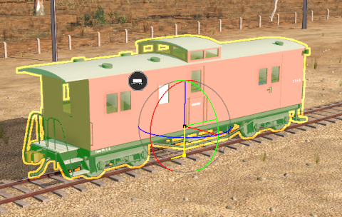 |
|
Despite their presence in the Fine Adjustment Tool 3D Anchor Frame the Red Green Blue Rotational Anchor lines and the Blue Vertical Anchor Line will NOT work on Rolling Stock Objects |
|
The Object Anchor (the central black dot) will move the selected rolling stock object or objects in any horizontal direction but they will always be attached to the nearest track spline |
|
The Green Horizontal Anchor Line will move the selected rolling stock object or objects along the track |
|
The Red Horizontal Anchor Line will move the selected rolling stock object or objects horizontally off the track but they will always be attached to the nearest track spline |
| Steps: To move a Rolling Stock Object or objects:- |
|
Left Click and Drag the object or objects |
|
release the objects on or close to their new track position |
|
|
Fine Adjustment: Decouple Rolling Stock Objects
|
|
|
|
|
|
|
|
All decoupling operations between Rolling Stock Objects are performed using just a Left Click and Drag. |
| To decouple a rake of joined rolling stock objects from a consist (for example, the first or last 5 wagons), Shift + Left Click on each of the objects to be selected and then drag them away from the consist |
|
A rolling stock object or objects in the middle of a consist can also be decoupled. This will break the consist into 3 sections.
Fine Adjustment: Couple Rolling Stock Objects
|
|
|
|
|
|
|
|
All coupling operations between Rolling Stock Objects can be performed using just a Left Click and Drag or through the objects Context Menu. |
Options:
Using "Click and Drag"
Consider the following simple situation:-
Using the Context Menu
Using the same situation as above, the isolated guard van and the gondola wagon at the end of a consist are to be coupled together.
There are two possible outcomes depending on which object has the Context Icon
| Using a more complex example involving multiple objects from several different consists. The selected wagons shown below are to form a single consist based on the loco. |
|
| The loco was the last object to be selected so it has the Context Icon. The Context Menu is opened and the option Merge into Single Train is selected with the result as shown below. |
|
| The wagons and loco have been combined into a single consist but not necessarily in a useful order. Left Click and Drag the incorrectly placed vehicles to their correct positions. |
| A selected rolling stock object, or a group of selected rolling stock objects, will have a Context Icon that opens a Context Menu. The icon design will vary between object types. |
To open a selected rolling stock object's Context Menu choose one of the following:-
| Options: |
|
Left Click its Context Icon OR |
|
Press the T key |
|
|
|
|
You cannot add rolling stock assets to a Scrapbook but you can create and save Consist Assets that have multiple rolling stock objects
| Steps: To create a Consist Asset:- |
|
select the consist - Double Left Click on the consist or Shift + Left Click on individual items |
|
open the consist Context Menu - Left Click on its icon or press the T key |
|
select the option Save to Consist Asset... |
|
enter a name and an optional description for your new Consist Asset and click the icon |
| The consist will appear as a Train asset in the Assets Palette |
|
|
|
Fine Adjustment: Object Height Problem Solutions
|
|
|
|
|
|
|
| Two Anchor Points on the Blue vertical Anchor line determine the height of an endpoint or an object above the ground. |
|
the Object Height Anchor, which is normally Black but turns Green when it is selected, controls the height of the object (including spline Endpoints) above the ground. This Anchor point can be moved vertically by the tool pointer using the Blue vertical Anchor line |
|
the Ground Height Anchor, which is Yellow, marks the position of the object on the ground. This Anchor point cannot be moved vertically by the tool pointer but its height can be changed by setting the Tool Options Palette Height value |
| It is common for both height anchors to be at the same height but there are many situation where the two will be at different heights. The examples below show situations where the two are at different heights and the height of the Object Height Anchor will need to be adjusted. |
|
|
If the Tool Options Palette and Info Palette are not visible on the screen then refer to Notes: Palettes at the top of this document.
|
|
|
Notes:
The height of a Rolling Stock Object (locomotive, wagon, etc) CANNOT be altered. These objects are always tied to the height of the track where they have been placed. |
|
A more complex alternative method is to use the Surveyor Compass Rose, the Info Palette and the Tool Options Palette .
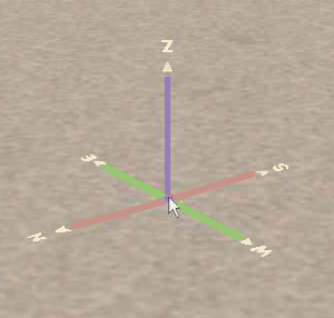
The Surveyor Compass Rose |
| Steps: Use the Compass Rose:- |
|
Right Click on the terrain at a point which has the height that will be used by the object. This will position the Surveyor Compass Rose and record its data as the Focus |
|
In the Info Palette open the Focus controls by a Left Click on the small Right Arrowhead to the left of the Focus label |
|
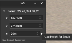 |
The Info Palette stores the positional data, including the Height (the z: value), of the Compass Rose under the label Focus |
|
|
Left Click on the white Down Arrowhead next to the z: (height) value and select the menu option Use Height for Brush . This will transfer the Focus: z value to the Tool Options Palette Height setting |
|
Open the Context Menu for the object (or spline endpoint) |
|
Select the option Apply Height or Apply Height to this Spline Endpoint |
|
|
 |
Keyboard Shortcut: F |
|
|
The Marquee Tool allows areas of your Trainz World to be selected for Scrapbook and baseboard operations |
|
The Marquee Tool is a general purpose tool for marking out areas of baseboards (or empty space) for:- |
|
|
the mass selection of objects for deletion, movement and creating Scrapbooks |
|
adding, deleting, painting and converting baseboards |
|
|
Various function of this tool use the Scrapbook Palette Tool Options Palette Info Palette Filter Palette and the Assets Palette . If these palettes are not visible on the screen when required then refer to Notes: Palettes at the top of this document. |
|
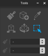 |
| Tool Targets The Marquee Tool has no Target options so it has no drop down menu list |
| This tool has a range of tasks:- |
|
Select objects for moving, deleting and copying into a scrapbook |
|
Add and delete one or multiple baseboards |
|
Set the resolution of one or multiple baseboards |
|
Set the texture and height of an area including multiple baseboards |
|
| Tool Actions The Marquee Tool has no Action options so it has no drop down menu list |
|
|
|
The Marquee Tool draws out a rectangular area, the Marquee Selection Area, on the route. Any objects (including ground heights, ground textures and TurfFX/Clutter Effect Layers) that are inside the Marquee Selection Area or touched by its boundary will be selected. |
| Steps: To draw out a Marquee Selection Area:- |
|
In the Tools Palette Left Click on the Marquee Tool icon or press the F key |
|
Left Click and Drag over the area to be selected |
|
|
|
You can use the filters in the Filter Palette and Assets Palette to restrict the objects that will be selected in the Marquee Selection Area. See Marquee Assets Filter below for more details |
|
|
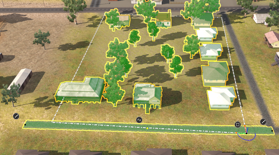
| In the image above:- |
|
a road spline at the bottom and a house at the lower left of the Marquee Selection Area have been touched by the drawn rectangle so they have been included in the selection. |
|
the Marquee Selection Area was drawn from the top left to the bottom right which places the Marquee Context Icon  at the bottom right of the rectangle. at the bottom right of the rectangle. |
|
the bottom right of the Marquee Selection Area also has a 3D Anchor Frame.
|
Like the Fine Adjustment Tool, a Marquee Selection Area has a 3D Anchor Frame. The Marquee Anchors are used to move, rotate and/or resize the objects within the selection area (including ground heights, ground textures and TurfFX/Clutter Effect Layers if they have been included in the palette filter) through 3D space. See the Marquee Anchor Controls for the details on using this tool. |
|
|
|
The road spline was the last object that was included in the selection area so its Context Icons are also present. |
| Shown in the image, but not highlighted, are the Ground Heights, Ground Textures and Effect Layers that are also included in the Marquee Selection Area. |
The Marquee Tool and the Palette Filters
|
|
|
|
|
|
|
|
The Filter Palette and Assets Palette can be used to restrict the objects selected by the Marquee Tool. |
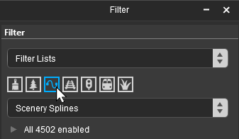 |
| Steps: To restrict the objects selected by the Marquee Tool:- |
|
In the Filter Palette set the Filter Action to Filter Selections |
|
In the Filter Palette select an Asset Icon or an Asset Type (e.g. Scenery Splines) |
|
In the Assets Palette enter an optional search text in the Search box to narrow down the type of object |
|
In the Tools Palette Left Click on the Marquee Tool or press the F key |
|
Left Click and Drag out the Marquee Selection Area around the objects to be selected |
| Only those objects identified in the filtered list will be selected by the Marquee |
|
|
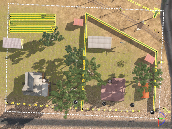 |
Using the Filters shown above, the Marquee Selection Area will include:-
|
all spline objects (excluding tracks) crossed by the selection area. See Note: below |
|
all ground textures |
|
all TurfFX/Clutter Effect Layers |
|
all ground heights |
| ...found within the Marquee Selection Area |
|
If a spline segment has one or both of its endpoints outside the Marquee Selection Area but the selection area crosses part of the segment then that segment will be selected |
|
|
Not included (highlighted) in the Marquee Selection Area, because they were not included in the filter, are:-
|
all scenery mesh objects (trees, grasses, buildings, etc) |
|
tracks and track objects |
|
|
|
|
| When a Marquee Selection Area is drawn or a Scrapbook is pasted in your Trainz World it will come with a 3D Anchor Frame at one corner of the selection area. This frame has some similarities to the one used with the Fine Adjustment Tool. |
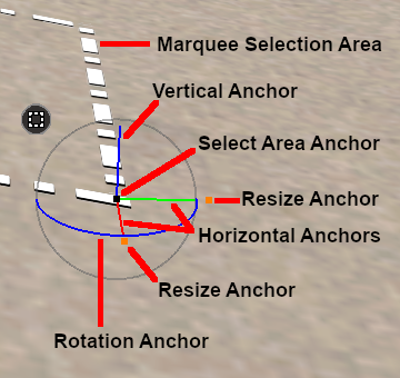 |
The controls provided by the Marquee Anchor Frame are:-
|
the Green and Red horizontal Anchors will move the Marquee Selection Area and all its contents‡ horizontally in the Anchor direction. Left Click and Drag left or right along the red or green horizontal Anchor line |
|
the Blue vertical Anchor will move the Marquee Selection Area with all its contents‡ up or down in the Anchor direction. Left Click and Drag up or down on the blue vertical Anchor line |
|
the Blue rotational Anchor will rotate the Marquee Selection Area with all its contents‡ in the direction of the rotation movement. Left Click and Drag clockwise or anticlockwise around the blue curved Anchor line |
|
there are no Green and Red rotational Anchors |
|
at the centre of the 3D Anchor Frame is a Select Area Anchor. Left Click and Drag this Anchor point to move the Marquee Selection Area with all its contents‡ in any horizontal direction |
|
each of the Green and Red horizontal Anchors has a resize Anchor, an orange coloured dot, located at its end. Left Click and Drag the orange anchor point left or right along its coloured Anchor line to resize the Marquee Selection Area and all its contents‡ in that specific direction. Objects that are in locked layers will not be affected by the resize action |
|
‡ Notes:
|
|
Contents for the Selection Area drawn using the Marquee Tool will always include Ground Heights, Textures and TurfFX/Clutter Effect Layers |
|
Contents for the Selection Area from a Scrapbook pasted into your Trainz World will only include those elements selected in the Scrapbook Palette Filter |
|
|
|
|
Notes:
|
| The Marquee Anchors will move/rotate:- |
|
the selected scenery objects. If the objects are in locked layers then they will NOT be moved |
|
the ground textures. As shown in two of the images below this will leave the original baseboard ground texture or grid pattern showing |
|
|
If you do not want to move everything that is in the Marquee Selection Area then set the filters in the Filter Palette and Assets Palette before using the Marquee Tool to only include those assets that you do want to move |
|
|
|
the TurfFX/Clutter Effect Layers. If an effect layer is locked then it will not be moved but it will still be deleted from the area that was covered by the original Marquee Selection Area |
|
the ground heights |
|
|
| The following images demonstrate the effect of using the Marquee Anchor Controls on the image shown at the top of this section as the starting point. |
Horizontal Anchor Shift
| |
The Green Horizontal Anchor Line has been used to shift the Marquee Selection Area to the left. Note that the 3 trees and a small building that were on the left of the Marquee Selection Area in the original image above at the start of this section have been replaced (overwritten) by the Marquee contents. Also note that the texture has been moved leaving a gap showing the original grid texture. |
|
| |
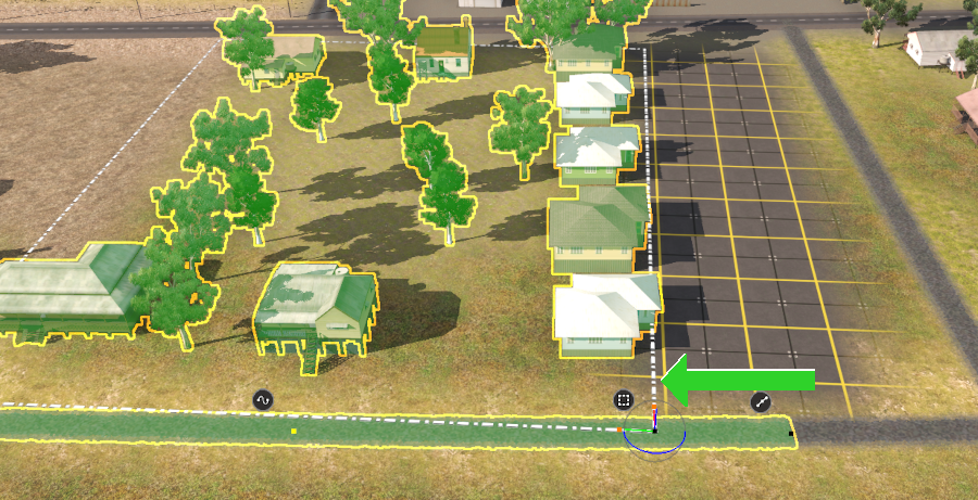 |
| |
|
Rotational Anchor Shift
| |
The Blue Rotational Anchor Arc has been used to rotate the Marquee Selection Area about 45° anti-clockwise. Again, anything that was originally in the area now covered by the Marquee Selection Area has been replaced by the contents of the Marquee. Also note that the texture has been moved leaving a gap showing the original grid texture. |
|
| |
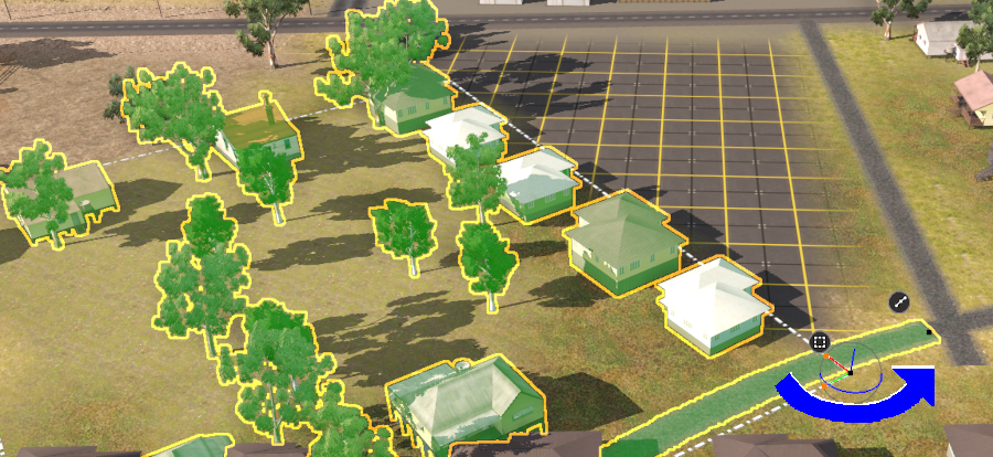 |
| |
|
Vertical Anchor Shift
| |
The Blue Vertical Anchor Line has been used to lift the Marquee Selection Area upwards. Note that the ground height, ground textures and any effect layers within the Marquee Selection Area have also been moved up. |
|
| |
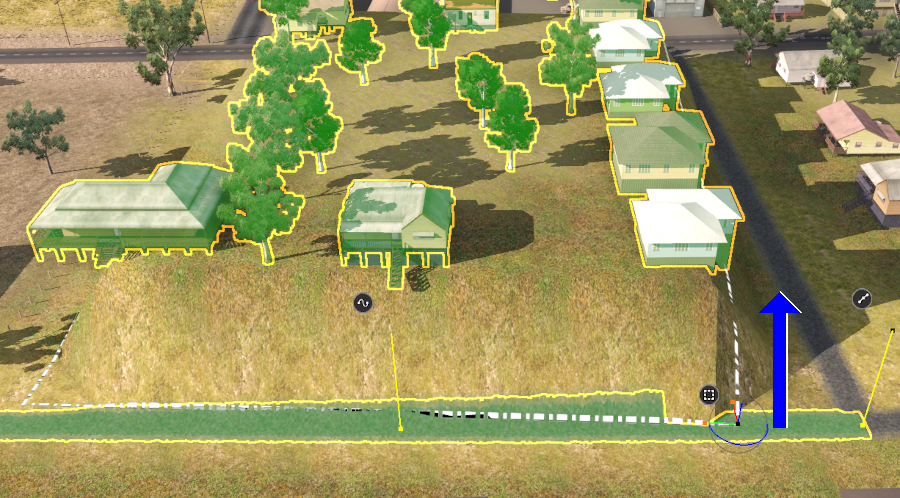 |
| |
|
|
The Scrapbook is a Surveyor 2.0 Clipboard that can hold multiple objects of different types. Like your operating system clipboard you can Cut or Copy selected objects into a new scrapbook and then Paste them anywhere in your route. The Scrapbook has additional features:- |
|
|
you can have multiple scrapbooks, that can be permanent or temporary, ready for use whenever Surveyor is started |
|
you can Paint a scrapbook into a scene, using the Brush Tool, with a range of control options and Brush Actions |
|
you can control which types of objects in a scrapbook are painted or pasted and how they are painted/pasted. You can alter these controls to suit different situations |
|
|
Notes:
|
| Scrapbooks, when created, will contain:- |
|
Ground Heights |
|
Ground Textures |
|
TurfFX/Clutter Effect Layers - if present |
|
Selected Objects - scenery items, splines, track, signals, etc |
|
But NOT Rolling Stock (Trains) . Rolling Stock consists can be saved for later use as new Consist Assets. See Rolling Stock Object Context Menu for the details. |
| The ground heights, ground textures and TurfFX/Clutter Effect Layers in the Marquee Selection Area will always be added to the scrapbook. You can use the filters in the Filter Palette and Assets Palette to control which visible objects in the selection area will also be added |
|
|
|
Notes:
|
|
Scrapbooks, when painted or pasted, can contain any combinations of:- |
|
Ground Heights |
|
Ground Textures |
|
TurfFX/Clutter Effect Layers |
|
Scenery Objects (Meshes) - individual buildings, trees, signals, etc |
|
Scenery Splines - roads, track, fences, etc |
| You have options in The Scrapbook Filters that will control which of these data types are added to your Trainz World and how they are added. |
|
|
Once an area has been marked out by the Marquee Tool a number of options become available.
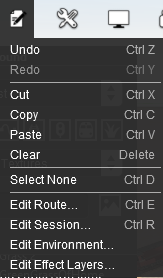 |
| The Surveyor Edit Menu will show some additional options specifically for the Marquee Tool:- |
| Cut |
the objects selected in the Marquee area (including the ground heights, ground textures and TurfFX/Clutter Effect Layers) will be copied and placed into a new Scrapbook. Any scenery objects (excluding ground heights, ground textures and effect layers) that are not in a locked layer will be removed from the Marquee area. This is the same as pressing the Ctrl + X keys |
| Copy |
the objects selected in the Marquee area (including ground heights, ground textures and TurfFX/Clutter Effect Layers) will be copied and placed into a new Scrapbook. This is the same as pressing the Ctrl + C keys |
| Paste |
the contents of the current Scrapbook will be pasted into the route at the cursor (focus) point. Which contents will be pasted and how they will be pasted are controlled by the Filters in the Scrapbook Palette (see Scrapbook Data for more details). This option will always be available with and without a Marquee area being marked if there is a scrapbook available to be pasted. This is the same as pressing the Ctrl + V keys |
| Clear |
the selected scenery objects that are not in locked layers will be removed from the Marquee area but NOT the selected ground heights, ground textures and TurfFX/Clutter Effect Layers. This is the same as pressing the Delete key |
| Select None |
the Marquee Selection Area boundary lines are removed from the route cancelling the selection process. Nothing that is inside the area will be removed. This is the same as pressing the Ctrl + D keys |
|
|
Adding a New Scrapbook
|
|
|
|
|
|
|
|
The Cut and Copy Scrapbook operations are also found in the Marquee Context Menu (see the Marquee Context Menu below). |
| You don't have to use the Marquee Tool to create a new Scrapbook. You can use the Free Move Tool or the Fine Adjustment Tool to select any number of objects and then press Ctrl + C . The selected objects, along with the ground heights, ground textures, and any TurfFX/Clutter Effect Layers, will be copied into a new Scrapbook |
|
When a new Scrapbook is created by a Cut (or press Ctrl + X ) or Copy (or press Ctrl + C ), it will appear in the Scrapbook palette with some basic details.
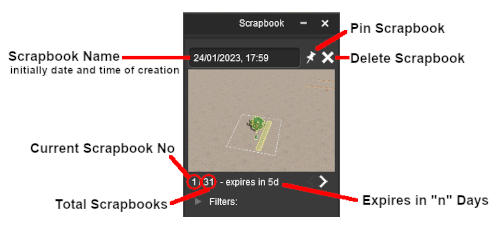 |
| The newly created scrapbook will be given:- |
|
a name consisting of the date and time of its creation |
|
a thumbnail |
| The thumbnail image will be taken using the current camera POV (point of view). To get a better image adjust the camera position and view to give the best possible shot of the Scrapbook objects before giving the Cut or Copy command
|
|
|
|
a scrapbook number (it will be inserted as the №1 scrapbook) |
|
an expiry date which will be set 5 days after its creation - this will countdown each day until 0 when the new scrapbook will be deleted |
|
|
Notes:
|
|
Scrapbooks use very little memory so there is no real limit to how many you can store in the palette but finding the one you want will be more difficult as the list grows longer |
|
Rolling Stock Objects cannot be added to a Scrapbook. The rolling stock Context Menu option Save to Consist Asset... performs some of the Scrapbook functions for rolling stock objects and consists |
|
Deleting a Scrapbook after it has been pasted does not delete the objects that it has added to the route |
|
|
There are two changes that can be made to the new scrapbook:-
 |
Give it a name - Left Click inside the Name Text Box and type a new name. To set its new name Left Click on the image OR press the Enter key |
 |
Make it permanent - Left Click the white Pin icon () to change it to blue. The scrapbook will no longer expire but it can still be deleted at any time |
| Pinned scrapbooks are always shown with a blue pin icon and the words "pinned, no expiry" displayed next to their scrapbook № |
| The Pinning of any scrapbook can be reversed so that it will then expire in 5 days time. Left Click the blue pin icon. |
|
|
|
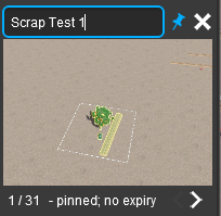 |
Once a scrapbook has been Pinned it becomes an asset and will appear in Content Manager
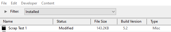
The scrapbook can be uploaded to the DLS and saved as a CDP file.
| You can archive your scrapbooks as CDP files to keep the number of installed scrapbooks to a minimum. If an archived scrapbook is needed then you can use the Import Content Files option in Content Manager to add it to the Scrapbook Palette . It can be deleted from the palette later, when no longer needed. |
|
|
The Marquee Context Menu creates, deletes, converts and paints individual or multiple baseboards. It also creates and pastes scrapbooks. |
To open the Context Menu for a Marquee Selection Area Left Click on its Context Icon or press the T key.
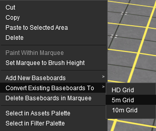 |
|
Marquee Context Menu Options |
|
| Cut |
removes the objects in the selection area from the route and moves them into the Scrapbook. Ground heights, ground textures and TurfFX/Clutter Effect Layers will be copied, not cut. Has the same effect as pressing the Ctrl + X keys |
|
| Copy |
copies the objects in the selection area and moves them into the Scrapbook. Has the same effect as pressing the Ctrl + C keys |
|
| Paste to Selected Area |
pastes the objects in the currently selected Scrapbook into the selection area.
|
When pasted from a scrapbook the objects will add to or replace all other objects, splines, textures, ground terrain and effect layers in the Marquee Selection area depending on the settings in the Scrapbook Filters |
|
|
| Delete |
deletes the objects in the selection area except for the ground heights, textures and effect layers. Has the same effect as pressing the Delete key |
|
| Paint Within Marquee |
if a texture has been selected in the Assets Palette then that texture will be painted inside the selection area using the settings in the Tool Options Palette . If no texture has been selected then this option will be greyed out |
|
| Set Marquee To Brush Height |
changes the ground height of the selection area to the brush height in the Tool Options Palette |
|
| Convert Baseboards To |
converts the resolution of the entire baseboard or baseboards covered by the selection area to one of three options - HD Grid (in Trainz Plus only), 5m Grid and 10m Grid . If the selection area covers any empty spaces outside the existing baseboards then NO NEW baseboards will be created in those spaces. See Notes: below |
|
| Delete Baseboards in Marquee |
deletes the entire baseboard or baseboards covered by the selection area. See Notes: below |
|
| Select in Assets Palette |
sets the Filter Palette to All Content and highlights in the Assets Palette the most common ground texture used in the Marquee Selection area |
|
| Select in Filter Palette |
sets the Filter Palette to All Content and highlights in the Filter Palette the most common ground texture used in the Marquee Selection area |
|
|
|
|
Notes:
|
| |
|
The Convert Baseboards To and Delete Baseboards in Marquee options will affect the entire baseboard or baseboards that contain the Marquee Selection Area even if the selection area only covers a small part of a baseboard.
|
|
It is NOT RECOMMENDED that you mix HD Resolution baseboards with 10m or 5m Resolution baseboards in the same route. The boundaries between HD and non-HD baseboards will have display issues. If you are going to use the HD Resolution then it is recommended that the entire route should be Upgraded to HD. You can mix both 5m Resolution and 10m Resolution baseboards in the same non-HD Resolution route. See Upgrading a Route to HD below for more details. |
|
|
|
The Marquee is a powerful tool for adding, deleting and changing the properties of multiple baseboards |
Add, Delete, Convert Baseboards
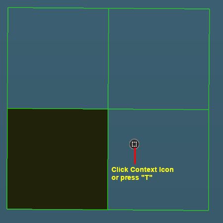
|
In Trainz Plus you can Upgrade an existing 5m Resolution or 10m Resolution route entirely to HD Resolution. See Upgrading a Route to HD below for more details. |
|
|
| Steps: To add, delete and convert baseboards:- |
|
In the Tools Palette Left Click on the Marquee Tool or press the F key |
|
Left Click and Drag to draw out the Marquee Selection Area area where the new baseboards will be added or the existing baseboards will be deleted or converted. |
| The Marquee Selection Area, shown with a green border in the image on the left, covers the existing baseboard (black, bottom left) and where 3 new baseboards will be created. The Marquee has a Context Icon as shown in the image. |
|
Left Click on the Context Icon or press the T key to open up the Marquee Context Menu (see Marquee Context Menu above). |
|
Create, Convert, Delete |
|
To Add new baseboards select the context option Add New Baseboards > then select a resolution from two or three sub-options, HD Grid (in Trainz Plus only), 5m Grid and 10m Grid . If existing baseboards have also been covered by the selection area then they will NOT be converted to the new resolution.
|
It is NOT RECOMMENDED that you mix HD Resolution baseboards with 10m or 5m Resolution baseboards in the same route. It should be ALL HD or none. You can mix both 5m Resolution and 10m Resolution baseboards in the same route but NOT with HD Resolution baseboards |
|
|
|
To Convert highlighted baseboards to a different Grid Resolution select the context option Convert Existing Baseboards To > then select a resolution from two or three sub-options, HD Grid (in Trainz Plus only), 5m Grid and 10m Grid . If the selection area covers any empty spaces outside the existing baseboards then NO NEW baseboards will be created in those spaces
|
It is NOT RECOMMENDED that you mix HD Resolution baseboards with 10m or 5m Resolution baseboards in the same route. It should be ALL HD or none. Mixing 5m Resolution and 10m Resolution baseboards in a route is OK |
|
|
|
To Delete the selected baseboards select the context option Delete Baseboards in Marquee . Note: An entire baseboard will be deleted even if the selection area only covers a small part of the baseboard. The Ctrl + Z keys can Undo the deletion.
|
|
|
Baseboard Ground Height
|
|
|
|
|
|
|
|
The Marquee Selection Area can be used to set the height of entire baseboards or just a selected section of one or more baseboards |
| Steps: To set the height of the baseboards or area under the Marquee Selection Area:- |
|
in the Tool Options Palette enter the required ground height into the Height setting. Note: the Grade setting has no effect when used with the Marquee tool |
|
In the Tools Palette Left Click on the Marquee Tool or press the F key |
|
Left Click and Drag to draw out the Marquee Selection Area area so that it covers the area that will have its height set. This can include multiple baseboards and empty spaces. Note: If empty spaces are included in the Marquee Selection Area then new baseboards will be created in those empty spaces |
|
Left Click on the Context Icon or press the T key to open up the Marquee Context Menu (see Marquee Context Menu above). |
|
select the Context Menu option Set Marquee to Brush Height . If the Marquee extends over empty space then new baseboards will be created at the set Height value. |
|
Baseboard Ground Texture
|
|
|
|
|
|
|
|
The Marquee Selection Area can be used to set the ground texture of entire baseboards or just a selected section of one or more baseboards |
| Steps: To paint the baseboards or area under the Marquee Selection Area with a ground texture:- |
|
from the Assets Palette Left Click on a ground texture. Selecting a texture will automatically select the Brush Tool |
|
in the Tool Options Palette set the brush Scale setting and any other required controls |
|
in the Tools Palette Left Click on the Marquee Tool or press the F key |
|
Left Click and Drag to draw out the Marquee Selection Area area so that it covers the area that will be painted with the texture. This can include multiple baseboards and empty spaces. Note: If empty spaces are included in the Marquee Selection Area then new baseboards will be created in those empty spaces |
|
Left Click on the Context Icon or press the T key to open up the Marquee Context Menu (see Marquee Context Menu above). |
|
select the Context Menu option Paint Within Marquee . If the Marquee extends over empty space then new baseboards will be created and covered with the selected ground texture. The new baseboards will be created at the Default altitude for the set Region or at 0m if no region has been set. |
|
| The Free Move Tool and Fine Adjustment Tool are able to select multiple objects that can then be manipulated as a single object. The objects can be of different Asset Types (e.g. Scenery Meshes and Scenery Splines) and they do not have to be in the same layer. |
| You can also use the Marquee Tool to select objects but this will also select the ground heights, ground textures and TurfFX/Clutter Effect Layers as well as the objects. |
|
|
The possible manipulations are:-
|
bulk physical moves - horizontal, vertical and rotations. Objects in Locked layers cannot be moved |
|
cloning or duplication - all the cloned objects will be placed into the current Active Layer |
|
Selecting Multiple Identical Objects
|
|
|
|
|
|
|
|
Both the Free Move Tool and the Fine Adjustment Tool can move and clone (duplicate) single and multiple objects. The Marquee Tool can also move and clone objects but it will include the ground heights, ground textures and any TurfFX/Clutter Effect Layers in the cloning and moving operations. |
|
| You can quickly select all nearby identical objects by a Double Left Click on an object. |
| This also applies to all the wagons in a consist. Double Left Click on any one of them to select all of them - they DO NOT have to be identical wagons. |
|
| A forest of many different trees. Only one has been selected. |
Double Left Click on a tree to select all the identical trees in the forest. |
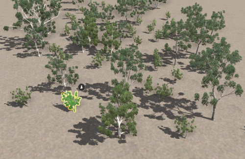 |
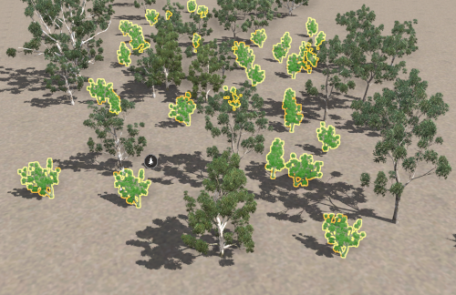 |
| Shift + Double Left Click on another object. It and all its identical copies will be added to the selection. |
|
Selecting and Moving Multiple Objects
|
|
|
|
|
|
|
Multiple objects can be selected and moved with the Free Move Tool and the Fine Adjustment Tool.
|
Notes: Mass Moves
| The objects DO NOT have to be:- |
|
the same type. They can be a mixture of scenery splines and mesh objects |
|
in the same layers but objects in Locked layers cannot be moved |
|
|
|
| You can also use the Marquee Tool to move objects but this will also move the ground heights, ground textures and TurfFX/Clutter Effect Layers as well as objects. |
|
|
|
You can easily clone single and multiple selected objects. If you have selected a group of objects they DO NOT have to be the same type - you can, for example, select scenery objects and scenery splines. |
|
Notes: Layers and Cloning
|
|
the objects can be in different layers |
|
the layers can be locked and the objects will still be cloned |
|
all the cloned objects will be placed into the current Active Layer which must be Unlocked |
| For more information on layers see The Info Palette at the end of this document. |
|
|
| Steps: To clone an object or a group of objects:- |
|
In the Tools Palette select either the Free Move Tool or the Fine Adjustment Tool |
|
Left Click on a single object or Shift + Left Click for multiple objects |
|
Ctrl + Left Click and Drag on any of the selected objects |
|
|
Bulk Replace Assets Tool (Trainz Plus Only)
|
|
|
|
|
|
|
|
This tool is available in Trainz Plus only |
|
It will replace ALL seleted objects with a single selected replacement asset |
|
All objects, and its replacement, must be the same Asset Type |
|
The replacement will occur throughout the entire route |
|
This tool uses the Filter Palette and the Assets Palette . If these palettes are not visible on the screen then refer to Notes: Palettes at the top of this document. |
|
|
This tool is only available in Trainz Plus
In TRS22PE use the Surveyor Classic Bulk Asset Update/Replace option |
|
|
|
|
|
Before you reach Step 6 below it would be a good idea to either know the exact name of the asset you will be using as the replacement so you can quickly find it in the Assets Palette or have it visible in the Surveyor Trainz World View to select it with the Eyedropper tool |
|
| Steps: To use the Bulk Replace Assets Tool:- |
|
In the Filter Palette open the Filter Toggles by a Left Click on either the small arrowhead on the left of the Enabled box or on the "Enabled" message itself. |
| |
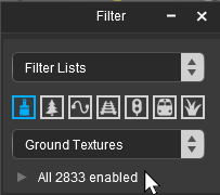 |
This will open the Filter Palette Toggle List of assets and a separate Search text box. The Toggle List list is identical to the list shown in the Assets Palette except that each item can be toggled or switched ON or OFF by the check mark on its left. |
|
Use the Filter Palette Asset Type icons or the Drop Down List to select the TYPE of asset to be replaced. Note: All the assets to be replaced must be of the same type (e.g. ALL scenery splines or ALL track objects) |
| You can bulk replace:- |
|
|
one or more different Ground Textures with a single Ground Texture and NOT with any other type of asset |
|
 |
one or more different Scenery Meshes with a single Scenery Mesh and NOT with any other type of asset. None of the meshes can include track‡ |
|
 |
one or more different Scenery Splines with a single Scenery Spline and NOT with any other type of asset. None of the splines can include track‡ |
|
 |
one or more different Track Splines with a single Track Spline and NOT with any other type of asset. Fixed Track assets are NOT track splines |
|
 |
one or more different Track Objects with a single Track Object and NOT with any other type of asset |
| ‡ this includes fixed assets and splines with built-in track (e.g. industries, bridges, tunnels) |
| You cannot bulk replace:- |
 |
 |
Rolling Stock (locomotives, wagons) |
|
|
Presets (effect layers) |
|
|
Optional: Use the Filter Palette Search text box to narrow down the list |
| |
|
Select (highlight) and toggle ON the assets that will be replaced in the route (the process is summarised in the steps below)
| Steps: To toggle ON an asset, or a subset of the assets, shown in the list:- |
| Clear the Existing Toggles: |
 |
In the Toggle List select one of the assets such as the asset to be replaced, or the first of a group of assets to be replaced |
 |
Press Ctrl + A to highlight them all |
 |
Left Click on the Toggle icon of any one of the assets to set them all to OFF |
| Set the New Toggles: |
 |
To clear all the highlighting and select an asset to be replaced Left Click on the name of the asset
If more then one asset is to be replaced then use Shift + Left Click and/or Ctrl + Left Click to highlight the additional assets |
 |
Left Click on the Toggle icon of the selected asset or on any one of the seleted assets to set them all to ON |
|
|
|
|
In the Filter Palette select the Filter Disabled option from the Filter Actions drop down menu
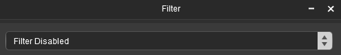 |
| This will break the connection between the Filter Palette and the Assets Palette and will set the Assets Palette to show All Content |
|
|
|
|
In the Assets Palette select the Replacement Asset (only one can be selected and it must be of the same Type as those selected to be replaced)
You can use the Assets Palette Search text box to narrow down the list of assets (or use the Eyedropper) but DO NOT use the selection tools (the asset type icons or drop down list) in the Filter Palette |
|
In the Assets Palette filtered list Right Click on the replacement asset to open its menu |
| |
 |
Select the last item, Bulk Replace Filtered Assets |
|
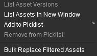 |
|
WARNING:
The Bulk Replace will occur throughout the ENTIRE route |
|
|
| |
With the exception of unusually small or simple routes, a progress bar will be shown. For large routes the replacement process may take a few minutes.
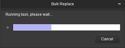
|
|
Notes:
|
|
Clicking the Cancel button will terminate the replacement process at the point shown by the position of the progress bar but some, or many, of the replacements will have already been made. |
|
After termination, or after the replacement process has been completed, pressing the Ctrl + Z keys will Undo all the replacements |
|
|
|
Upgrading a Route to HD (Trainz Plus Only)
|
|
|
|
|
|
|
|
This option is only available in Trainz Plus |
|
Upgrading an entire route to HD is recommended over mixing HD Resolution and non-HD Resolution baseboards in the same route, but there are limitations to upgrading that must be considered beforehand |
| You can convert (Upgrade) an entire 5m Resolution or 10m Resolution route to HD Resolution in a single step but there are some important limitations. See the Notes: below. |
 |
| Steps: To Upgrade a route to HD:- |
|
Left Click on the Surveyor Tools Menu icon |
|
Left Click on the option Upgrade Route |
| A progress bar will show the status of the conversion process which may take several minutes depending on the size of the route. At the conclusion of the upgrade you will be given a report indicating that the process was successful or it has failed because of errors. See Notes: below. |
|
|
|
| A typical HD Upgrade report would look like:- |
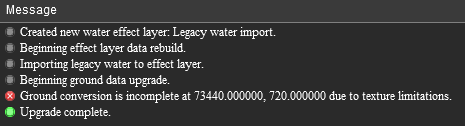 |
The report indicates that:-
 |
Legacy Water was detected and was converted to a Water Effect Layer |
 |
the baseboard at compass co-ordinates x = 73440m, y = 720m
has exceeded the limit of 16 ground textures |
 |
the HD Upgrade was completed successfully |
|
|
|
If the Info Palette is not visible on the screen then refer to Notes: Palettes at the top of this document. Some Info Palette functions will also require the Assets Palette and the Tool Options Palette .
|
|
| This palette can be easily overlooked but it has some very useful features:- |
|
naming objects |
|
providing precise data and control over the "focus" - the position of the cursor |
|
providing precise data and control over the position and orientation of objects (it can be used instead of the Free Move Tool and the Fine Adjustment Tool) |
|
identifying and setting the "home" layer and binding layer of a selected object |
|
used for locking and unlocking a selected objects layer |
The components of the Info Palette are identified in the image below.
|
All the positional data and controls in the Info Palette are defined in the following ways:- |
|
| x: |
is ALWAYS the North-South compass direction regardless of the direction that an object is facing |
| y: |
is ALWAYS the East-West compass direction regardless of the direction that an object is facing |
| z: |
is ALWAYS the Vertical direction (perpendicular to the compass directions) regardless of how an object has been rolled or tilted |
|
Notes:
|
|
distances are measured in metres from the North-West corner of the first baseboard. If that baseboard is later deleted then distances will still be measured from its original and now "virtual" North-West corner. |
|
+ positive distances are in the South , East and Up directions |
|
- negative distances are in the North , West and Down directions |
|
New boards added to the North of the first baseboard will have negative x coordinates and new boards added to the West of the first baseboard will have negative y coordinates. |
|
|
|
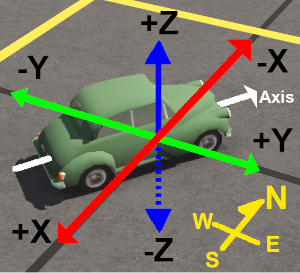 |
| All the Focus, Position and Rotation settings have drop down menus that allow values to be transferred to and from other settings and other tools. |
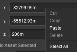
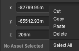 |
| Steps: |
|
Left Click on the small arrowhead icon next to one of the labels Focus: Pos: or Rot: to open up its list of settings |
|
Right Click inside an Info Palette setting box |
| The first time the popup menu is opened it will only show two active options - Paste and Select All. |
| Paste |
will paste the contents of your Operating System (Windows, MacOS) clipboard into the setting. If data is already present then the pasted data will be added to it, not replace it. To replace the contents use the Select All option first (see below) then the Paste option |
|
| Select All |
will highlight the contents of the selected setting. You can also achieve this with a Left Click and Drag across the contents of the setting |
|
|
Right Click inside the same Info Palette setting box |
| Once the value in a setting has been selected (highlighted) the popup menu will show all options as active. |
| Cut |
will copy the contents of the selected setting into your Operating System clipboard. The contents will then be deleted from the setting |
|
| Copy |
will copy the contents of the selected setting into your Operating System clipboard without deleting it |
|
| Delete will delete the contents of the selected setting. You can also achieve this with a Left Click and Drag across the contents and then press the Delete key |
|
|
|
Next to the z: value in both the Focus and Position settings is a small white down arrowhead. Left Click on the arrowhead to open its menu.
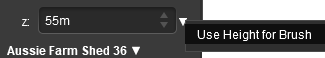 |
There is only one option in the sub-menu.
| Left Click on the Use Height for Brush option to copy the current z: value to the Tool Options Palette Height setting. |
|
|
|
The Focus shows the current position and height of the Cursor object |
|
If it has not been deleted you can identify the North-West corner of the original (first) baseboard by entering 0 as the Focus: x: and y: co-ordinates |
|
|
"Asset Name" refers to the name of the asset as displayed in the Assets Palette and in Content Manager. This is not the same as the Object Name (see the next section) |
| You must have an object (or objects) selected for the Asset Name data to be shown. If more than one object has been selected then you will be shown the name for the last object selected |
 |
If different objects (with different <kuid> codes) have been selected then a count of the additional objects will be added. The (+2) shown in the object name in the image on the left indicates that 2 additional different objects are in the group of selected objects. |
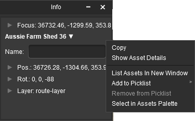 |
| Steps: To Open the Menu of a selected Asset or Assets |
|
Next to the Asset Name is a small white Arrowhead icon. Left Click on the arrowhead to open the asset menu |
|
|
|
| Asset Name Menu Options |
| Copy |
copies the asset name and <kuid> into your operating systems clipboard. If more than two assets have been selected then only the first two will be copied |
|
| Show Asset Details |
opens a new window showing the image and description of the selected object |
|
| List Assets in New Window |
opens up Content Manager and lists all the selected objects |
|
| Add to Picklist |
adds selected objects to a Picklist |
|
| Remove from Picklist |
NOT WORKING (a known bug)
use this same option found in the Filter Palette or Content Manager instead |
|
| Select in Assets Palette |
selects and highlights the selected object in the Assets Palette |
|
|
|
|
"Object Name" refers to the name that you give to an object |
| You can give any object in your Trainz World an identifying name. In some cases a name is vital for AI and session operations, in other cases it will be needed as a display feature - for example: to be shown on a station nameboard. You must have the object (or objects) selected for this option to be available. If more than one object has been selected then only the last object (the one with the Context Icon) will be given a name |
|
| Steps: To name (or rename) an object:- |
|
In the Info Palette Left Click inside the Name: text entry box |
|
If the Name: text entry box is greyed out and cannot be selected then the layer containing the object is locked. Use the Layer: Layer Info and Controls to unlock the layer. Then reselect the object and try again |
|
|
Enter or edit the name |
|
Press the Enter key |
|
KNOWN BUG: Changes to the name of a Track Object will not save unless something else in the route is also edited. The following additional step is a workaround when renaming Track Objects |
|
If you are renaming a track object (e.g. a signal) then move a non-track object (e.g. a tree) before saving. If you have already edited something else in the route but not yet saved then this step will not be necessary |
|
|
|
If more than one object has been selected then only the last selected object, the one with the Context Icon, will be named. |
|
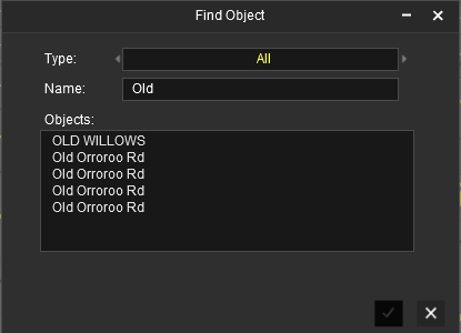 |
| There is no ban on two or more objects using the same name |
|
In the image shown on the left there are 4 objects all named Old Orroroo Rd.
This will not cause any problems for scenery objects apart from finding the exact one you want with the Finder Tool ( Ctrl + F keys) as shown in the image on the left - Which of the 4 "Old Orroroo Rd" objects is the one that I need?
|
WARNING:
Duplicate names will cause problems for Industries (including passenger enabled stations), Locomotives, Track Marks, Triggers, Switches, Signals, etc that have to be identified to control the operation of a session. |
| These objects must have unique names |
|
|
Position Info and Controls
|
|
|
|
|
|
|
| You must have an object (or objects) selected for the Position Info and Controls to be edited. If more than one object has been selected then you will be shown the data for the last object selected |
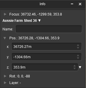 |
| Steps: To Edit the Position Info of a selected Object or Objects |
|
Left Click on the Arrowhead icon in front of the Pos: label. This will open its data for editing. |
|
The x: , y: and z: text boxes show the current position of the object with z: showing the height. These values can be edited to move the object or objects to a new position but CARE will be needed - see Notes: below. If any selected object is in a locked layer then it will not move.
| On the right of each data entry box is a pair of Up/Down arrow controls. Left Click and Drag up or down on these to adjust the position in smaller increments down to centimetres |
|
|
The z: (height) value can be copied into the Tool Options Palette Height setting (open the down arrowhead next the z: value) and select the option Use Height for Brush |
|
|
|
Notes:
|
|
If you enter an x: or y: value that is "out in empty space" (beyond the edge of a boundary baseboard) then the objects will be moved to that position and may vanish from view. The Undo ( Ctrl + Z ) command can be used to immediately reverse the move or the Marquee Tool can be used to add a baseboard under the "floating" objects if you know where they are located. You can also use the Marquee Tool to select those objects and delete them. Note: The compass rose cannot be moved beyond the edge of a boundary baseboard |
|
The z: value gives the current height of the object (or the last object selected). Entering a value that is above or below the ground height will move the object to that height. In the case of multiple selected objects the height of each will be adjusted up or down by the same value, they will not be all set to the same height. |
|
|
Rotation Info and Controls
|
|
|
|
|
|
|
| You must have an object (or objects) selected for the Rotation Info and Controls to be edited. If more than one object has been selected then you will be shown the data for the last object selected |
|
If this option is greyed out (shown as Rot: ) and cannot be opened then the selected object (splines for example) cannot be rotated using this method or it cannot be rotated at all. It may be possible to rotate it using some of the Rotational Anchors found in the Fine Adjustment Tool |
|
|
Notes:
|
|
the Info Palette is best used to show and edit the layer and binding layer assignments of individual selected objects |
|
operations such as creating, deleting, merging, renaming, moving and hiding layers are performed using the Layers Palette |
|
layers can be Locked and Unlocked using the Info Palette or the Layers Palette but the Layers Palette is often the better choice for these tasks |
|
| You must have an object (or objects) selected for the layer data to be shown and edited. The name of the layer containing the selected object (or last selected object) will be shown next to the Layer: (below the Name: text entry box). |
|
If the layer name is shown as - then multiple objects have been selected and not all of them are in the same layer. Deselect all the objects and only select a single object |
|
|
Assigning Objects to a Different Layer
|
|
|
|
|
|
|
|
The Active Layer is the layer used by the Placement Tool when objects are added to your Trainz World. |
| A selected object or group of objects can be assigned to a different layer. If multiple objects have been selected then they do not all have to be in the same layer BUT their current layer or layers must be unlocked. The destination layer can be locked and this will not stop the layer reassignment. |
|
WARNING:
|
Setting a layer for an object or a group of selected objects will move them to that layer |
|
If objects are moved from one layer group to another (such as from the Route Layers to the Session Layers) then it will change where those objects are saved (in the Route or in the Session) |
|
|
| Options: To set current layer to the Active Layer:- |
| If the Select Layer button is greyed out |
 |
then the selected object is now assigned to the current Active Layer so there is no need to use this option |
| If it is NOT greyed out |
 |
then the selected object is now assigned to a layer that is not the current Active Layer. Left Click on the Select Layer button to switch the Active Layer to the same layer as the object
|
|
Assigning Objects to a Binding Layer
|
|
|
|
|
|
|
|
The Binding Layer, or Bound Layer as it is also called, is a tool used in the development of your Trainz World |
|
Setting a Binding Layer allows you to temporarily assign an object to a second layer while it is still in its original layer. The object will then take on the properties (Locked or Unlocked, Hidden or Visible) of both layers. |
|
Setting a Binding Layer has NO effect on where an object is saved (in the Route or the Session) or on any of the properties of the object |
Assigned
Layer |
|
Binding
Layer |
|
Object
Status |
|
 Unlocked Unlocked |
or None |
Unlocked |
 LOCKED LOCKED |
or or None |
LOCKED |
| Unlocked |
LOCKED |
LOCKED |
|
 Visible Visible |
or None |
Visible |
 HIDDEN HIDDEN |
or or None |
HIDDEN |
| Visible |
HIDDEN |
HIDDEN |
|
|
| In Summary:- |
|
If the Assigned Layer or the Binding Layer of an object is Locked then the object will be Locked |
|
If the Assigned Layer or the Binding Layer of an object is Hidden then the object will be Hidden |
|
Notes:
|
|
Objects in a Hidden Layer cannot be seen and therefore, cannot be selected, deleted or moved |
|
The Layers Palette is the ONLY way to create, delete, name and hide layers |
|
|
Some examples of using the Binding Layer:-
Example 1: |
| The problem: |
You need to stop an object from being selected so that you can you move other objects on or around it |
| The solution: |
Use the Layers Palette to create a new empty layer and lock it. Set the Binding Layer of the object to the new locked layer. The object will then be locked so it cannot be selected or moved even though its original layer is unlocked. When the edit has been completed delete the empty locked layer you just created to unlock all its bound objects and remove all their bindings
|
| Example 2: |
| The problem: |
A group of objects (e.g trees) are blocking access to another object. |
| The solution: |
Use the Layers Palette to create a new empty layer and hide it. Set the Binding Layer of the blocking objects to the new hidden layer. The blocking objects will no longer be visible and cannot be selected even though their original layer is still visible. When the edit has been completed delete the empty hidden layer you just created to make all its bound objects visible and remove all their bindings
|
|
| As an example, the image below shows what you will see for a single object that has had:- |
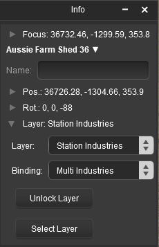 |
|
its assigned layer changed (in the example from "route-layer" to "Station Industries") |
|
its binding layer set (in the example to "Multi Industries") |
|
the newly assigned layer is locked so you have the option to UNLOCK it |
|
the newly assigned layer is not the Active Layer so you have the option to make it the Active Layer |
|
|
More information on creating, editing and using Layers can be found on the Trainz Wiki at:-
|
Trainz Wiki
 |
More Tutorials and Guides to Using Trainz
|
|
|
Related Links
|
|
This page was created by Trainz user pware in January 2023 and was last updated as shown below.