How to Use S20 Tools
m (→Placement Tool Options) |
m (cleanup and clarifications) |
||
| Line 281: | Line 281: | ||
<tr valign="top"> | <tr valign="top"> | ||
<td width=20>[[image:DotPoint.JPG|link=]]</td> | <td width=20>[[image:DotPoint.JPG|link=]]</td> | ||
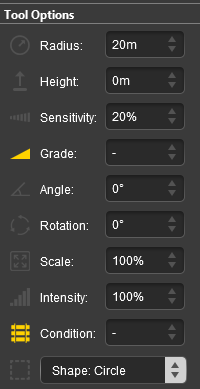
| − | <td>The <span style="font-size: 15px; font-weight: 700; color: gold; background-color: black;"> Grade </span> | + | <td>The <span style="font-size: 15px; font-weight: 700; color: gold; background-color: black;"> Grade </span> is defined as '''height''' (vertical) over '''distance''' (horizontal) converted to a percentage figure. So a grade of 100% (the maximum allowed) would mean a slope formed by the height and distance both being the same value (e.g. a height increase of 50m over a distance of 50m). A vertical slope (a cliff) would have an infinite grade which is currently impossible in Surveyor.</td> |
</tr> | </tr> | ||
</table> | </table> | ||
| Line 1,028: | Line 1,028: | ||
</tr> | </tr> | ||
<tr valign="top"> | <tr valign="top"> | ||
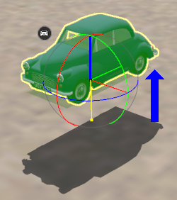
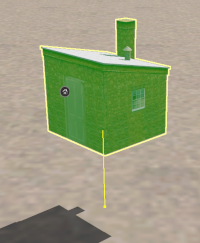
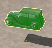
| − | <td colspan=2><br>The object will be moved to the set height above (or below) the terrain. The vertical yellow line shown in the second image on the left indicates the height change. The small yellow dot at the base of the line is the terrain ''' | + | <td colspan=2><br>The object will be moved to the set height above (or below) the terrain. The vertical yellow line shown in the second image on the left indicates the height change. The small yellow dot at the base of the line is the terrain '''attachment point''' for the object.<br> |
<br> | <br> | ||
<table bgcolor=#000000 width=600 cellpadding=2> | <table bgcolor=#000000 width=600 cellpadding=2> | ||
| Line 1,110: | Line 1,110: | ||
<td>The <span style="font-size: 15px; font-weight: 700; color: white; background-color: black;"> Height </span> setting in the '''Tool Options Palette''' can also be applied to a '''selected''' spline '''endpoint''' or '''segment'''. If the '''endpoint''' or '''segment''' is at the end of the spline then the following new endpoints and segments will be added at the new height.<br> | <td>The <span style="font-size: 15px; font-weight: 700; color: white; background-color: black;"> Height </span> setting in the '''Tool Options Palette''' can also be applied to a '''selected''' spline '''endpoint''' or '''segment'''. If the '''endpoint''' or '''segment''' is at the end of the spline then the following new endpoints and segments will be added at the new height.<br> | ||
The height change can be made by:- | The height change can be made by:- | ||
| − | *directly entering a value in the '''Tool Options''' | + | *directly entering a value in the '''Tool Options''' <span style="font-size: 15px; font-weight: 700; color: white; background-color: black;"> Height </span> setting, '''OR''' |
| − | *selecting the | + | *selecting the <span style="font-size: 15px; font-weight: 700; color: white; background-color: black;"> Apply Height </span> option from the objects '''Context Menu'''</td> |
</tr> | </tr> | ||
</table> | </table> | ||
| Line 1,133: | Line 1,133: | ||
<tr valign="top"> | <tr valign="top"> | ||
<td> </td> | <td> </td> | ||
| − | <td>The <span style="font-size: 15px; font-weight: 700; color: gold; background-color: black;"> Grade </span> | + | <td>The <span style="font-size: 15px; font-weight: 700; color: gold; background-color: black;"> Grade </span> is defined as '''vertical rise''' divided by '''horizontal distance''' converted to a percentage figure. So a grade of 100% (the maximum allowed) would mean a gradient formed by both measurements having the same value (e.g. a rise of 50m over a distance of 50m). A vertical grade (such as up a cliff face) would have an infinite grade which is currently impossible in Surveyor.</td> |
</tr> | </tr> | ||
</table> | </table> | ||
| Line 1,245: | Line 1,245: | ||
<table bgcolor=#ffffb0 width=756 cellpadding=2> | <table bgcolor=#ffffb0 width=756 cellpadding=2> | ||
<tr valign="top"> | <tr valign="top"> | ||
| − | <td> | + | <td>[[image:NotePad.PNG|link=]]</td> |
| − | The object will be identified by its | + | <td><span style="font-size: 17px; font-weight: 700;">Notes:'''</span><br> |
| + | ---- | ||
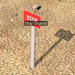
| + | The object will be identified by its name appearing in a <span style="font-weight: 700; font-size: 15px; color: white; background-color: black;"> ToolTip </span> below the mouse pointer (image shown left).<br> | ||
<br> | <br> | ||
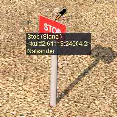
Leave the mouse pointer in place for a few seconds and additional information about the object will be shown, its '''<kuid>''' code, '''Author''' and (if available) some of its description (image shown below left). | Leave the mouse pointer in place for a few seconds and additional information about the object will be shown, its '''<kuid>''' code, '''Author''' and (if available) some of its description (image shown below left). | ||
| Line 1,266: | Line 1,268: | ||
<table bgcolor=#ffffb0 width=356 cellpadding=2> | <table bgcolor=#ffffb0 width=356 cellpadding=2> | ||
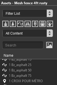
<tr valign="top"> | <tr valign="top"> | ||
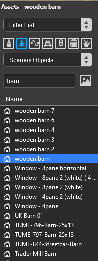
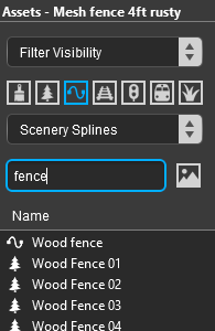
| − | <td>The type of object and its name will be automatically shown (highligted in grey) in the '''Asset Palette''' filters as shown in the image left.<br> | + | <td>[[image:NotePad.PNG|link=]]</td> |
| + | <td><span style="font-size: 17px; font-weight: 700;">Notes:'''</span><br> | ||
| + | ---- | ||
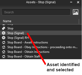
| + | The type of object and its name will be automatically shown (highligted in grey) in the '''Asset Palette''' filters as shown in the image left.<br> | ||
<br> | <br> | ||
'''Left''' click on the object name in the '''Asset Filter List''' to select it (highlight in blue) and switch control to the '''Placement Tool''' | '''Left''' click on the object name in the '''Asset Filter List''' to select it (highlight in blue) and switch control to the '''Placement Tool''' | ||
| Line 1,651: | Line 1,656: | ||
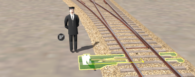
<td>Situations where this feature is useful include:-<br> | <td>Situations where this feature is useful include:-<br> | ||
* placing '''Track Marks''' and '''Triggers''' above or beside the track so that they are not hidden by consists parked on top of them | * placing '''Track Marks''' and '''Triggers''' above or beside the track so that they are not hidden by consists parked on top of them | ||
| − | * repositioning switches, signals, track signs closer to or further away from the track | + | * repositioning switches, signals, track signs closer to or further away from the track - particularly useful if the track object was originally created for a different gauge track |
</td> | </td> | ||
</tr> | </tr> | ||
| Line 1,713: | Line 1,718: | ||
</tr> | </tr> | ||
<tr valign="top"> | <tr valign="top"> | ||
| − | <td colspan=2>Rotating a track object does not change its distance from the | + | <td colspan=2>Rotating a track object does not change its distance from the track or its height. |
</td> | </td> | ||
</tr> | </tr> | ||
| Line 1,839: | Line 1,844: | ||
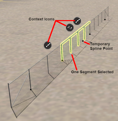
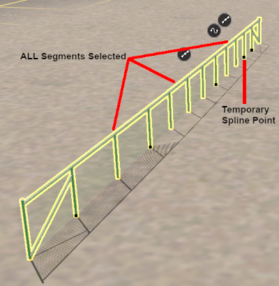
<td>To select '''ALL''' the segments in a spline, '''Dbl-Left''' click on a segment<br> | <td>To select '''ALL''' the segments in a spline, '''Dbl-Left''' click on a segment<br> | ||
<br> | <br> | ||
| − | The segment you double | + | The segment that you double-clicked will have the temporary endpoint added</td> |
</tr> | </tr> | ||
</table> | </table> | ||
| Line 1,857: | Line 1,862: | ||
If you had selected:- | If you had selected:- | ||
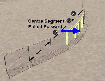
| − | *only a single spline segment then only that segment will be moved and the adjacent segments that were not selected will have their shapes | + | *only a single spline segment then only that segment will be moved and the adjacent segments that were not selected will have their shapes (but not their endpoints) adjusted |
| − | *multiple spline segments then those segments will be moved and the adjacent segments that were not selected will have their shapes | + | *multiple spline segments then those segments will be moved and the adjacent segments that were not selected will also have their shapes adjusted |
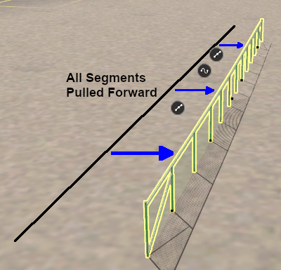
| − | *the entire spline then '''ALL''' the segments will be moved | + | *the entire spline then '''ALL''' the segments and endpoints will be moved |
</td> | </td> | ||
</tr> | </tr> | ||
| Line 1,875: | Line 1,880: | ||
<tr valign="top"> | <tr valign="top"> | ||
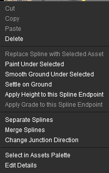
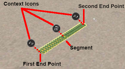
<td width=420>[[image:ContextIconsSpline_S20.png|link=]]</td> | <td width=420>[[image:ContextIconsSpline_S20.png|link=]]</td> | ||
| − | <td>Splines have two | + | <td>Splines have two different '''Context Icons''' that lead to two slightly different '''Context Menus'''. |
| − | + | *one context icon and menu for each '''endpoint''' | |
| − | + | *one context icon and menu for the '''segment''' | |
| + | If multiple segments have been selected then the last segment added to the selection will have the context icons. If all the segments were selected by a '''Dbl-Click''' then the segment that was clicked will have the icons.<br> | ||
<br> | <br> | ||
'''Left''' click on an icon to open its '''Context Menu'''.</td> | '''Left''' click on an icon to open its '''Context Menu'''.</td> | ||
| Line 2,055: | Line 2,061: | ||
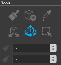
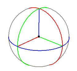
<tr valign="top"> | <tr valign="top"> | ||
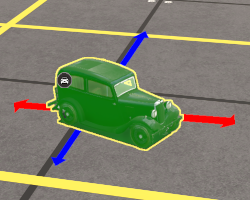
<td width=100><span style="font-weight: 900; font-size: 15px; color: white; background-color: red;">RED</span> <span style="font-weight: 900; font-size: 15px; color: white; background-color: green;">GREEN</span></td> | <td width=100><span style="font-weight: 900; font-size: 15px; color: white; background-color: red;">RED</span> <span style="font-weight: 900; font-size: 15px; color: white; background-color: green;">GREEN</span></td> | ||
| − | <td> | + | <td>rotations around the '''X''' and '''Y''' axis lines</td> |
</tr> | </tr> | ||
<tr valign="top"> | <tr valign="top"> | ||
| Line 2,103: | Line 2,109: | ||
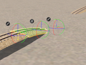
<td width=250>[[image:FineAdjustZMove_S20.png|link=]]<br>Scenery object after a '''Z''' axis vertical move</td> | <td width=250>[[image:FineAdjustZMove_S20.png|link=]]<br>Scenery object after a '''Z''' axis vertical move</td> | ||
<td width=20> </td> | <td width=20> </td> | ||
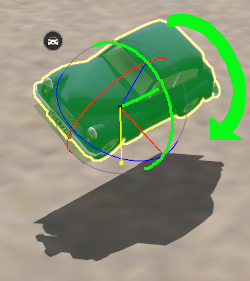
| − | <td width=250>[[image:FineAdjustYawMove_S20.png|link=]]<br>Scenery object after a "green" axis | + | <td width=250>[[image:FineAdjustYawMove_S20.png|link=]]<br>Scenery object after a "green" axis rotation</td> |
<td width=480> | <td width=480> | ||
<table bgcolor=#000000 width=480 cellpadding=2> | <table bgcolor=#000000 width=480 cellpadding=2> | ||
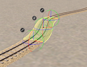
| Line 2,369: | Line 2,375: | ||
*the '''XYZ''' horizontal axes lines can be selected and used | *the '''XYZ''' horizontal axes lines can be selected and used | ||
*the '''blue''' circular rotation line (around the '''Z''' axis) can be selected and used | *the '''blue''' circular rotation line (around the '''Z''' axis) can be selected and used | ||
| − | *the '''red''' circular | + | *the '''red''' circular line can be selected and used |
| − | *the '''green''' circular | + | *the '''green''' circular line '''CANNOT''' be selected |
</td> | </td> | ||
</tr> | </tr> | ||
Revision as of 09:04, 15 January 2023
The information in this Wiki Page applies to Surveyor 2.0 (S20) as found in Trainz Plus.
This document is still being written
Contents |
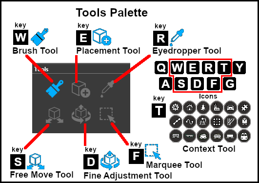
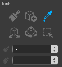
The Tools Palette
 |
|
|||||||||||||||||
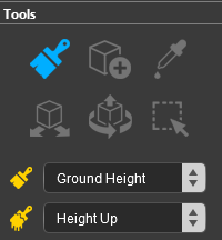
The Brush Tool
| Keyboard Shortcut: W | The Brush Tool "Paints" the Terrain, Ground Textures, Effect Layers and Scrapbook Scenes in a Route |
When selected, the Brush Tool has two drop down menu lists.
 |
|
|||||||||
Ground Height
|
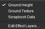
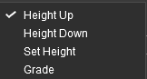
When the Ground Height Target is selected, the second drop down box will give a choice of several Ground Height tools.
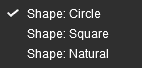
| The choices are:- | |
|
 |
| The available brush tool options are shown in the Tool Options Palette with a Gold coloured icon next to their names. Those options that have their icon greyed out will be ignored, but they can still be edited. | ||||||||||||||||||||||||||||||||||||
Height Up/Height Down 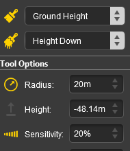 |
Set Height 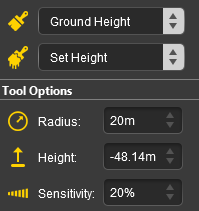 |
Grade 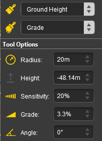 |
|
|||||||||||||||||||||||||||||||||
|
Ground Texture
|
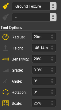
When the Ground Texture Target is selected, the second drop down box will be disabled - there are no brush texture tool choices.
The available brush tool options are shown in the Tool Options Palette with a Gold coloured icon next to their names. Those options that have their icon greyed out will be ignored, but they can still be edited.
 |
|
||||||||||||||||||||||||||||
|
Scrapbook Data
|
|
The Scrapbook Brush
When the Scrapbook Data Target is selected, the second drop down box will give a choice of two Scrapbook Data tools.
| The choices are:- | |
|
|
|
| The available brush tool options are shown in the Tool Options Palette with a Gold coloured icon next to their names. Those options that have their icon greyed out will be ignored, but they can still be edited. | |||||||||||||||||||||||||||||||
Scrapbook Brush 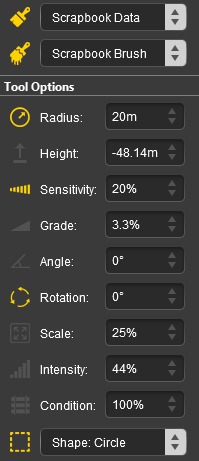 |
Scrapbook Clone 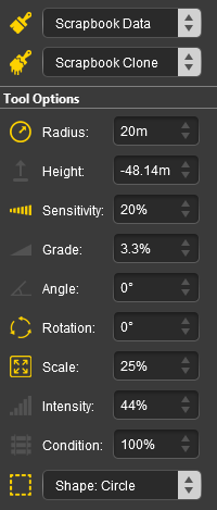 |
|
|||||||||||||||||||||||||||||
|
The Scrapbook Palette 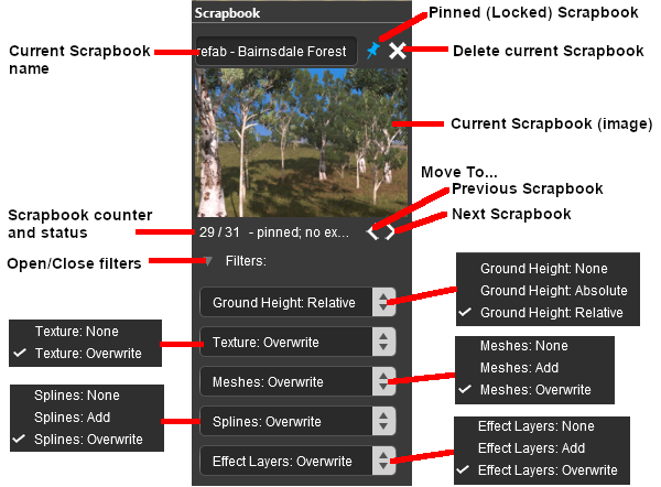 |
|
|||||||||||||||||||||||||||||||||||||||||||
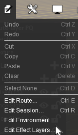
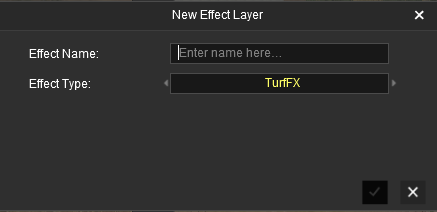
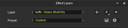
Edit Effect Layers...
When this Target is selected, the Edit Effect Layers options will appear. This is the same as selecting Edit Effect Layers ... from the Trainz Edit Menu.
 |
 |
 |
 |
More information on creating and editing Effect Layers can be found on the Trainz Wiki at:- |
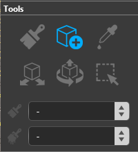
The Placement Tool
| Keyboard Shortcut: E | The Placement Tool Adds Objects to a Route |
|
When selected, the Placement Tool has no drop down menu lists.
 |
|
|||||||||||||||
The first step is to identify and select the particular object that you want to add to the route.
Placing a Scenery Mesh Object
Individual "non-spline" scenery objects that are not attached to track are often referred to in Trainz terminology as Scenery Mesh Objects.
![]() In the Asset Palette either:-
In the Asset Palette either:-
|
OR |
|
|
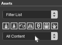
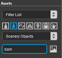
| To narrow down the filter list type part of the object name into the Search Text Box. For example if you have selected Scenery Objects and want to find "barns", then type "barn" (UPPER/lower case does not matter). |
 |
|
|
|
Placing a Scenery or Track Spline
Start the process of laying a track or spline by identifying and selecting the spline as described in steps ![]() to
to ![]() above. Then continue by following the steps listed below.
above. Then continue by following the steps listed below.
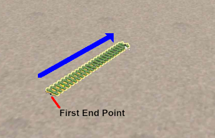 |
"Click on the spot" as shown in Step |
|
| Move the mouse in the direction you want to lay the spline or track. The spline will follow the mouse wherever you move it. | ||
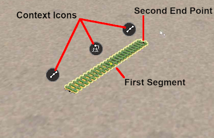 |
When you have the pointer in the final position for the first spline segment, Left click the mouse. This will anchor the second spline endpoint. The spline between the two endpoints is the first spline segment.
|
|
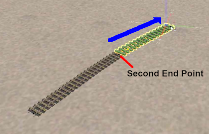 |
Left click on the new endpoint and move the mouse in the direction you want to continue laying the spline or track. The spline will follow the mouse wherever you move it. | |
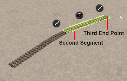 |
When you have the pointer in the final position for the second spline segment, Left click the mouse. This will anchor the third spline endpoint and produce new Context Icons for the second segment. | |
| Repeat Steps |
Spline Segment Heights
When you start adding a spline to a route it will always be placed at the height of the terrain regardless of the Tool Options Height setting.
However, you can set the height of the last segment that was added and this will set the height of all the segments added from that point.
| Lay the first spline segment which will be added at the terrain ground height | |
| Enter a value in the Tool Options Height and press the Enter key | |
| The endpoints of the current spline segment will immediately be adjusted to the new height setting | |
| Continue laying spline segments. Each new segment will be added at the new height | |
Placement Tool Options
The Tool Options Palette Height setting for Scenery Mesh Objects, Scenery Splines and Track Splines when using the Placement Tool does not show a gold coloured icon which indicates an "active" control setting but the setting is active.
Mesh Object Tool Options
 |
 |
|
|||||||||
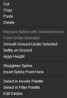
Spline Tool Options
Splines have two Placement Tool settings in the Tool Options Palette.
 |
|
||||||||||||||||||
|
Deleting Placed Objects
To delete objects either:-
|
OR |
|
The Eyedropper Tool
| Keyboard Shortcut: R | The Eyedropper Tool Identifies and Selects Objects in a Route |
|
When selected, the Eyedropper Tool has no drop down menu lists.
Quick Steps
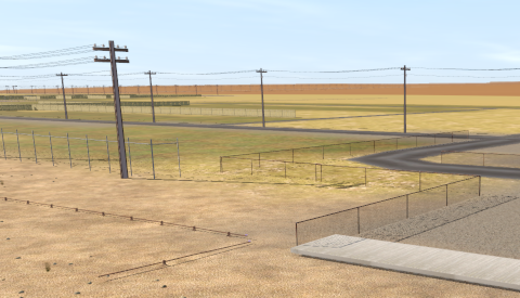
![]() With the Eyedropper Tool selected, move the mouse pointer (which will now be an eyedropper symbol) onto any object in view.
With the Eyedropper Tool selected, move the mouse pointer (which will now be an eyedropper symbol) onto any object in view.
  |
|
Narrowing the Search
Sometimes (or often) a scene will be too crowded with different scenery objects to be able to use the Eyedropper Tool to easily select a single object. In these cases additional options are available to help "remove the clutter".
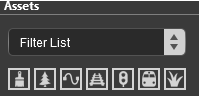
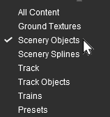
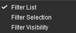
At the top of the Assets Palette is a drop down box which controls how the Eyedropper Tool works with the filters that you set.
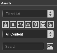 |
The drop down box will provide three options:-
|
These options work with the Asset Filters to help narrow the search for a specific object or type of object that is in the route.
|
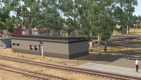
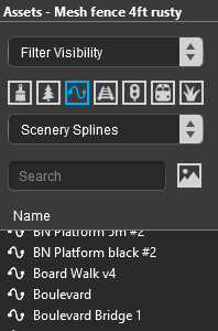
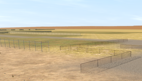
As an example the following images show the progressive application of a Visibility Filter.
 |
 |
|
 |
 |
|
 |
 |
|
The Free Move Tool
| Keyboard Shortcut: S | The Free Move Tool Moves Objects Around a Route |
|
When selected, the Free Move Tool has no drop down menu lists.
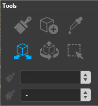 |
|
|||||||||||||
For Scenery Mesh Objects
Individual "non-spline" scenery objects that are not attached to track are often referred to in Trainz terminology as Scenery Mesh Objects.
Moving a Scenery Mesh Object
 |
|
Set the Height for a Scenery Mesh Object
When placed in a route by the Placement Tool a scenery object will take the height of the terrain as its set height. It will be fixed to the terrain so when you move it around it will always be at the same height as the terrain it is over.
This can be changed to fix the object to a set height above or below the terrain.
 |
|
||||||
Mesh Object Context Menu
A selected scenery object, or a group of selected scenery objects, will have a Context Icon with a Context Menu. The icon design will vary between object types. Multiple objects can be selected by holding down the Shift key while Left clicking on each object.
To open an objects Context menu either:-
- Left click the Context Icon, OR
- Press the T key
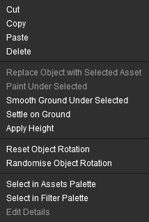 |
|
For Track Objects
Track Objects (signals, switches, speed signs, etc) are always attached to an existing track. They can be moved to new positions along the track and in Surveyor Classic that was the limit of their movement.
Surveyor 2.0 brings a new freedom of movement to track objects. They can be moved away from the track to the left or right as well as above and below the track. The operation of a track object is not affected by these changes.
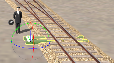
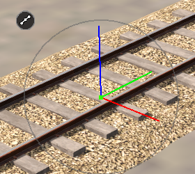
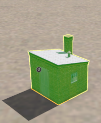
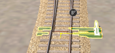
 Throw Lever track object in its original position |
|
||||||||||||||||||||||
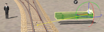
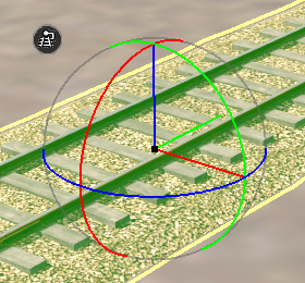
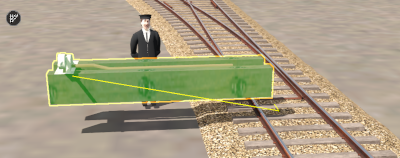 After being moved left with the Free Move Tool and up with the Height setting in the Tool Options Palette |
|||||||||||||||||||||||
The track object can still be moved along the track with the Free Move Tool.
|
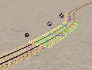
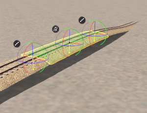
Track objects can also be rotated to the opposite side of the track.
 |
|
|||||||||
For Spline Objects (Including Track)
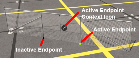
Scenery splines and track splines are defined by their endpoints. Splines are usually added to a route as a series of joined segments linked at the endpoints. Moving a spline can involve moving:-
- an endpoint, OR
- a segment, OR
- multiple segments including the whole length of the spline
Moving Spline Endpoints
 |
|
||||||||||||
Moving Spline Segments
Splines are frequently made of multiple segments joined together. You can easily move a spline by moving its segments, individually or as a group.
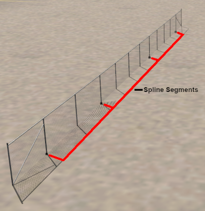 |
Not all splines will have endpoints at the ends of the spline. As shown in the image on the left, some splines will have an "endcap" that is attached to the start of the first segment and to the end of the last segment. The use of an endcap is a purely cosmetic effect - to give the spline a more distinctive appearance. |
 |
|
||||||
 |
|
|||||||||
| Use the mouse (Left button held down) to drag the selected segment(s) in any horizontal (XY) direction. If you had selected:-
|
 |
 |
Spline Object Context Menu
 |
Splines have two different Context Icons that lead to two slightly different Context Menus.
If multiple segments have been selected then the last segment added to the selection will have the context icons. If all the segments were selected by a Dbl-Click then the segment that was clicked will have the icons. |
The Fine Adjustment Tool
When selected, the Fine Adjustment Tool has no drop down menu lists.
For Scenery Mesh ObjectsIndividual "non-spline" scenery objects that are not attached to track are often referred to in Trainz terminology as Scenery Mesh Objects. You can move the objects freely in the XY (horizontal) plane by using a Left "click and drag" anywhere on the selected object except on a coloured line.
For Track ObjectsTrack Objects (signals, switches, speed signs, etc) are always attached to an existing track. They can be moved to new positions along the track and in Surveyor Classic that was the limit of their movement. Surveyor 2.0 brings a new freedom of movement to track objects. They can be moved away from the track to the left or right as well as above and below the track. The operation of a track object is not affected by these changes. The Fine Adjustment Tool works for Track Objects in the same way it does for Scenery Mesh Objects except for one important difference. All movements are restricted to the XY and Z planes with no rotations.
For Spline Objects (Including Track)Scenery splines and track splines are defined by their endpoints. Splines are usually added to a route as a series of joined segments linked at the endpoints. Moving a spline can involve moving:-
This section is still under construction
The Marquee Tool
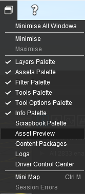
The Info PaletteThis palette can be easily overlooked but it has some very useful features. Its uses are:-
Trainz Wiki
This page was created by Trainz user pware in January 2023 and was last updated as shown below. |
||||||||||||||||||||||||||||||||||||||||||||||||||||||||||||||||||||||||||||||||||||||||||||||||||||||||||||||||||||||||||||||||||||||||||||||||||||||||||||||||||||||||||||||||||||||||||||||||||