How to Use S20 Tools
m (→For Spline Objects (Including Track)) |
(→For Spline Objects (Including Track)) |
||
| Line 1,457: | Line 1,457: | ||
=='''For Spline Objects (Including Track)'''== | =='''For Spline Objects (Including Track)'''== | ||
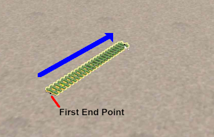
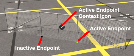
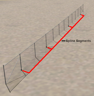
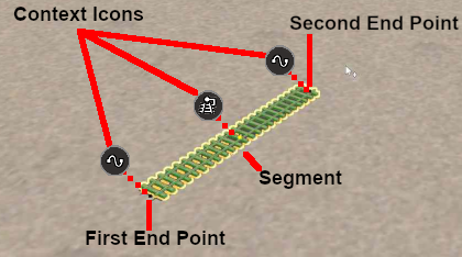
| − | Scenery splines and track splines are defined by their ''' | + | Scenery splines and track splines are defined by their '''endpoints'''. Splines are usually added to a route as a series of joined segments linked at the endpoints. Moving a spline can involve moving:- |
| − | *an | + | *an endpoint, <span style="font-size: 17px; font-weight: 700;">OR</span> |
*a segment, <span style="font-size: 17px; font-weight: 700;">OR</span> | *a segment, <span style="font-size: 17px; font-weight: 700;">OR</span> | ||
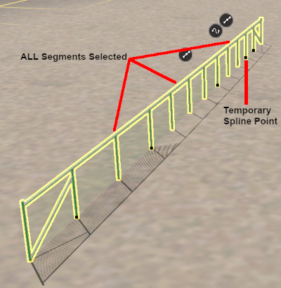
*multiple segments including the whole length of the spline | *multiple segments including the whole length of the spline | ||
<br> | <br> | ||
| − | <span style="font-weight: 700; font-size: 17px; color: white; background-color: blue;"> Moving Spline | + | <span style="font-weight: 700; font-size: 17px; color: white; background-color: blue;"> Moving Spline Endpoints </span><br> |
| − | To move an individual spline | + | To move an individual spline endpoint:-<b> |
<table width=900> | <table width=900> | ||
| Line 1,477: | Line 1,477: | ||
<tr valign="top"> | <tr valign="top"> | ||
<td>[[image:DotPoint2.JPG|link=]]</td> | <td>[[image:DotPoint2.JPG|link=]]</td> | ||
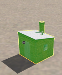
| − | <td>Select ('''Left''' click on) the spline | + | <td>Select ('''Left''' click on) the spline endpoint to be moved. This will be shown as '''green''' meaning '''active'''. Inactive spline endpoints are shown as '''black'''.</td> |
</tr> | </tr> | ||
<tr valign="top"> | <tr valign="top"> | ||
<td>[[image:DotPoint3.JPG|link=]]</td> | <td>[[image:DotPoint3.JPG|link=]]</td> | ||
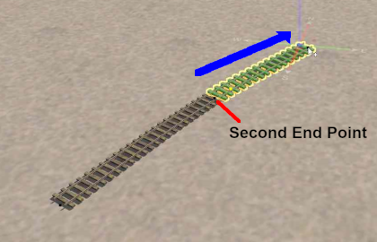
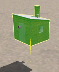
| − | <td>Use the mouse ('''Left''' button held down) to drag the spline | + | <td>Use the mouse ('''Left''' button held down) to drag the spline endpoint in any '''horizontal''' ('''XY''') direction.</td> |
</tr> | </tr> | ||
</table> | </table> | ||
| Line 1,491: | Line 1,491: | ||
<tr valign="top"> | <tr valign="top"> | ||
<td>[[image:NotePad.PNG|link=]]</td> | <td>[[image:NotePad.PNG|link=]]</td> | ||
| − | <td>The spline | + | <td>The spline endpoint will be '''fixed''' at its original height.</td> |
</tr> | </tr> | ||
</table> | </table> | ||
| Line 1,520: | Line 1,520: | ||
<tr valign="top"> | <tr valign="top"> | ||
<td>[[image:DotPoint2.JPG|link=]]</td> | <td>[[image:DotPoint2.JPG|link=]]</td> | ||
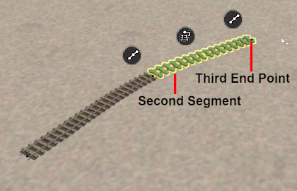
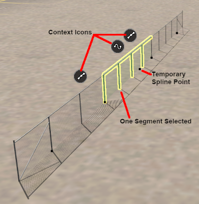
| − | <td>Select ('''Left''' click on) the spline segment to be moved - click anywhere between the two spline | + | <td>Select ('''Left''' click on) the spline segment to be moved - click anywhere between the two spline endpoints on the segment.<br> |
<br> | <br> | ||
The selected segment will be highlighted in '''green'''.<br> | The selected segment will be highlighted in '''green'''.<br> | ||
| Line 1,541: | Line 1,541: | ||
<tr valign="top"> | <tr valign="top"> | ||
<td>[[image:DotPoint3.JPG|link=]]</td> | <td>[[image:DotPoint3.JPG|link=]]</td> | ||
| − | <td>hold the <span style="font-weight: 700; font-size: 15px; color: white; background-color: black;"> Shift </span> key down and individually '''Left''' click between the | + | <td>hold the <span style="font-weight: 700; font-size: 15px; color: white; background-color: black;"> Shift </span> key down and individually '''Left''' click between the endpoints on each additional segment.<br> |
<br> | <br> | ||
The '''last''' segment that you click will have a '''Temporary Spline Point''' added.<br> | The '''last''' segment that you click will have a '''Temporary Spline Point''' added.<br> | ||
| Line 1,589: | Line 1,589: | ||
<tr valign="top"> | <tr valign="top"> | ||
<td width=420>[[image:ContextIconsSpline_S20.png|link=]]</td> | <td width=420>[[image:ContextIconsSpline_S20.png|link=]]</td> | ||
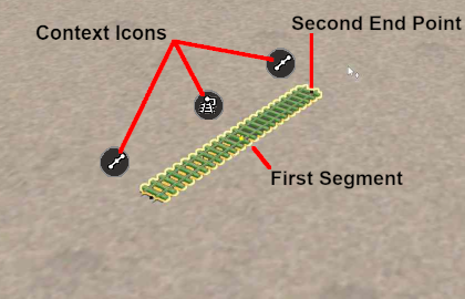
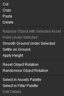
| − | <td>Splines have two separate '''Context Icons''' that lead to two slightly different '''Context Menus'''. One icon and menu is for each ''' | + | <td>Splines have two separate '''Context Icons''' that lead to two slightly different '''Context Menus'''. One icon and menu is for each '''endpoint''' and another icon and menu for the spline '''segment'''.<br> |
<br> | <br> | ||
| − | So a spline segment will have three '''Context Icons''' - one for each ''' | + | So a spline segment will have three '''Context Icons''' - one for each '''endpoint''' and one for the '''segment''' itself.<br> |
<br> | <br> | ||
'''Left''' click on an icon to open its '''Context Menu'''.</td> | '''Left''' click on an icon to open its '''Context Menu'''.</td> | ||
</tr> | </tr> | ||
</table> | </table> | ||
| − | + | <br> | |
<table> | <table> | ||
<tr valign="top"> | <tr valign="top"> | ||
| Line 1,602: | Line 1,602: | ||
<table> | <table> | ||
<tr valign="top"> | <tr valign="top"> | ||
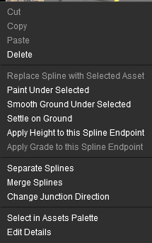
| − | <td width=220>[[image:SplineEndPointContextIcon_S20.png|link=]] <span style="font-weight: 700; font-size: 15px; color: white; background-color: black;">  | + | <td width=220>[[image:SplineEndPointContextIcon_S20.png|link=]] <span style="font-weight: 700; font-size: 15px; color: white; background-color: black;"> Endpoint Context Menu </span><br> |
[[image:ContextMenuSplineObject_S20.png|link=]]</td> | [[image:ContextMenuSplineObject_S20.png|link=]]</td> | ||
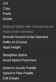
<td width=220>[[image:SplineSegmentContextIcon_S20.png|link=]] <span style="font-weight: 700; font-size: 15px; color: white; background-color: black;"> Segment Context Menu </span><br> | <td width=220>[[image:SplineSegmentContextIcon_S20.png|link=]] <span style="font-weight: 700; font-size: 15px; color: white; background-color: black;"> Segment Context Menu </span><br> | ||
[[image:ContextMenuSplineSegment_S20.png|link=]]</td> | [[image:ContextMenuSplineSegment_S20.png|link=]]</td> | ||
| + | <td> | ||
| + | <table width=680 bgcolor=#000000> | ||
| + | <tr valign="top"> | ||
| + | <td> | ||
| + | <table width=676 bgcolor=#ffffff> | ||
| + | <tr valign="top"> | ||
| + | <td><span style="font-weight: 700; color: white; background-color: black;"> Cut </span></td> | ||
| + | <td>remove the segment or segments and move them into the '''Scrapbook'''</td> | ||
| + | </tr> | ||
| + | <tr valign="top"> | ||
| + | <td><span style="font-weight: 700; color: white; background-color: black;"> Copy </span></td> | ||
| + | <td>copy the segment or segments and place them into the '''Scrapbook'''</td> | ||
| + | </tr> | ||
| + | <tr valign="top"> | ||
| + | <td><span style="font-weight: 700; color: white; background-color: black;"> Paste </span></td> | ||
| + | <td>paste the contents of the current '''Scrapbook'''</td> | ||
| + | </tr> | ||
| + | <tr valign="top"> | ||
| + | <td><span style="font-weight: 700; color: white; background-color: black;"> Delete </span></td> | ||
| + | <td>delete the segment, segments or endpoint. It has the same effect as pressing the <span style="font-weight: 700; font-size: 15px; color: white; background-color: black;"> Delete </span> key</td> | ||
| + | </tr> | ||
| + | <tr valign="top"> | ||
| + | <td><span style="font-weight: 700; color: white; background-color: black;"> Smooth Ground Under Selected </span></td> | ||
| + | <td>changes the height of the terrain under the segment or segments to match the set height of the spline (does not work on endpoints)</td> | ||
| + | </tr> | ||
| + | <tr valign="top"> | ||
| + | <td><span style="font-weight: 700; color: white; background-color: black;"> Settle on Ground </span></td> | ||
| + | <td>sets the height of the segment, segments or endpoint to match the height of the terrain beneath them ("drops them back to earth"). When used on segments the spline will follow the height changes of the terrain</td> | ||
| + | </tr> | ||
| + | <tr valign="top"> | ||
| + | <td><span style="font-weight: 700; color: white; background-color: black;"> Apply Height (to this Spline Endpoint) </span></td> | ||
| + | <td>sets the height of the segment, segment or endpoint to the value in the '''Tool Options''' <span style="font-weight: 700; font-size: 15px; color: white; background-color: black;"> Height </span> text box</td> | ||
| + | </tr> | ||
| + | <tr valign="top"> | ||
| + | <td><span style="font-weight: 700; color: white; background-color: black;"> Straignten Spline </span></td> | ||
| + | <td>forces a straight line (as far as possible) between the endpoints of a single segment. This option will be ticked if the segment has already been straightened</td> | ||
| + | </tr> | ||
| + | <tr valign="top"> | ||
| + | <td><span style="font-weight: 700; color: white; background-color: black;"> Insert Spline Point Here </span></td> | ||
| + | <td>inserts a new endpoint in a segment at the point where it was clicked Thi will split the segment in two</td> | ||
| + | </tr> | ||
| + | <tr valign="top"> | ||
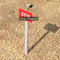
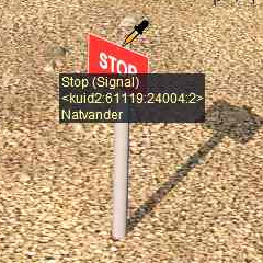
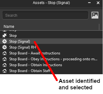
| + | <td><span style="font-weight: 700; color: white; background-color: black;"> Select in Assets Palette </span></td> | ||
| + | <td>identifies the selected spline in the '''Asset Palette''' like the '''Eyedropper Tool'''. If multiple different objects have been selected then the object with the '''Context Icon''' will be identified</td> | ||
| + | </tr> | ||
| + | <tr valign="top"> | ||
| + | <td><span style="font-weight: 700; color: white; background-color: black;"> Edit Properties </span></td> | ||
| + | <td>opens the '''Properties''' window of the selected object</td> | ||
| + | </tr> | ||
| + | </table> | ||
| + | </td> | ||
</tr> | </tr> | ||
</table> | </table> | ||
| − | |||
| − | |||
| − | |||
| + | </td> | ||
| + | </tr> | ||
| + | </table> | ||
| + | <br> | ||
| + | |||
| + | |||
| + | <br> | ||
<table> <!-- BEGIN Nav Buttons Table --> | <table> <!-- BEGIN Nav Buttons Table --> | ||
<tr valign="top"> | <tr valign="top"> | ||
Revision as of 21:56, 11 January 2023
The information in this Wiki Page applies to Surveyor 2.0 (S20) as found in Trainz Plus.
This document is still being written
|
|
|||||||||
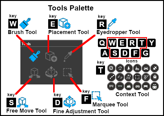
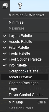
The Tools Palette
 |
|
|||||||||||||||||
The Brush Tool
The Brush Tool is used for painting the route. It can:-
When selected, the Brush Tool will show two drop down menu lists. |
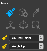 |
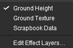
| The first drop down menu will set the Brush Target, the type of brush. The Targets are:- |
|||||
|
 |
|
|||
Ground Height
|
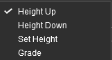
When the Ground Height Target is selected, the second drop down box will give a choice of several Ground Height tools.
| The choices are:- | |
|
 |
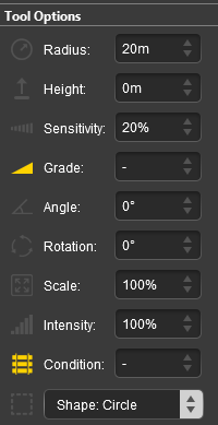
| The available brush tool options are shown in the Tool Options Palette with a Gold coloured icon next to their names. Those options that have their icon greyed out will be ignored, but they can still be edited. | ||||||||||||||||||||||||||||||||||||
Height Up/Height Down 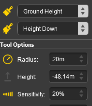 |
Set Height 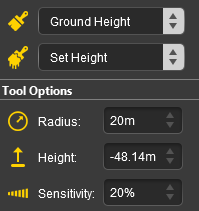 |
Grade 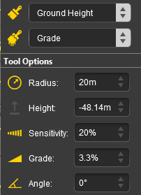 |
|
|||||||||||||||||||||||||||||||||
|
Ground Texture
|
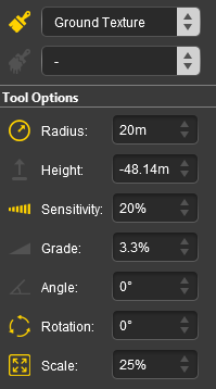
When the Ground Texture Target is selected, the second drop down box will be disabled - there are no brush texture tool choices.
The available brush tool options are shown in the Tool Options Palette with a Gold coloured icon next to their names. Those options that have their icon greyed out will be ignored, but they can still be edited.
 |
|
||||||||||||||||||||||||||||
|
Scrapbook Data
|
|
The Scrapbook Brush
When the Scrapbook Data Target is selected, the second drop down box will give a choice of two Scrapbook Data tools.
| The choices are:- | |
|
|
|
| The available brush tool options are shown in the Tool Options Palette with a Gold coloured icon next to their names. Those options that have their icon greyed out will be ignored, but they can still be edited. | |||||||||||||||||||||||||||||||
Scrapbook Brush 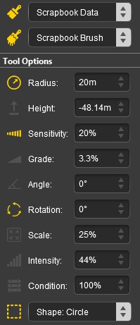 |
Scrapbook Clone 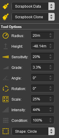 |
|
|||||||||||||||||||||||||||||
|
The Scrapbook Palette 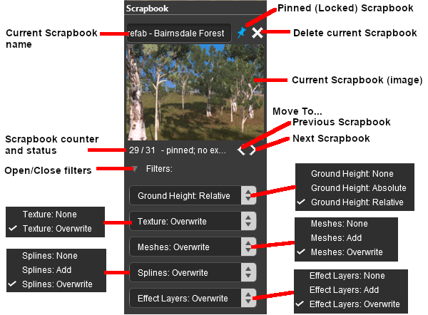 |
|
|||||||||||||||||||||||||||||||||||||||||||
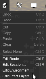
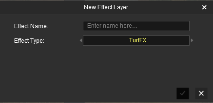
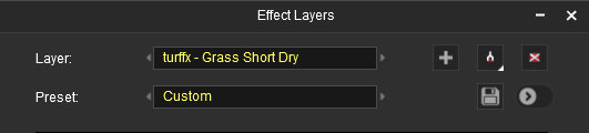
Edit Effect Layers...
When this Target is selected, the Edit Effect Layers options will appear. This is the same as selecting Edit Effect Layers ... from the Trainz Edit Menu.
 |
 |
 |
 |
More information on creating and editing Effect Layers can be found on the Trainz Wiki at:- |
The Placement Tool
The Placement Tool is used to add objects to the route.
The first step is to identify and select the particular object that you want to add to the route. Placing a Scenery Mesh ObjectIndividual "non-spline" scenery objects that are not attached to track are often referred to in Trainz terminology as Scenery Mesh Objects.
Placing a Scenery or Track SplineTo start the process of laying a track or spline, follow the steps listed above for placing a Scenery Mesh Object.
Placement Tool Options
Deleting Placed Objects
The Eyedropper Tool
|
||||||||||||||||||||||||||||||||||||||||||||||||||||||||||||||||||||||||||||||||||||||||||||||||||||||||||||||||||||||||||||||||||||||||||||||||||||||||||||||||||||||||||||||||||||||||||||||||||||||||||||||||||||||||||||||||||||||||||||||||||||||||||||||||||||||||||||||||||||||