M.clutter
m.clutter is a variation on the m.pbrmetalmasked material. It adds controlled fade distances which are intended to allow cross-fading between LODs. It does not include support for parallax mapping. All PBR materials are defined using a multitude of texture channels (not just a simple RGB image) which define various aspects of the material on a per-texel basis. One major advantage of this approach is that a single in-game material can be used to display various different real-world materials, rather than requiring multiple separate in-game materials with different parameters. Trainz uses a Metallic/Roughness style PBR workflow.
This pre-release material is intended for use with the Clutter Effect Layer, and will be tuned to suit that purpose to the detriment of any other possible use-case. While it is currently expected that the material will be available to other asset types, this availability is not locked in at the current time.
This page describes content format v4.6 and assumes that the FBX file format is used as a data source for any meshes.
Contents |
Cross-Fading
Cross-fading is expected to increase the cost of each LOD, but improve the visual transitions. The intent is that transitions can occur much closer to the camera, saving performance overall. If your use-case does not allow transitions to occur close to the camera, you may find that this material type is inappropriate for your needs. The typical use case is something which is small and heavily repeated in the scene, which requires high detail (eg. 100-500 polygons) at very close ranges (eg. up to about 10m) after which it can rapidly lose detail (eg. 500->100->10 or 100->25->5).
Cross-fading is implemented by using two different instances of this material per LOD level; one configured to fade out starting at a certain distance, and the other configured to fade in starting at the same distance. The nearer material is considered a higher LOD and should use more polygons. The asset might then be configured as follows:
- LOD0 - 0 .. 20m - Material A (no fade in, fade out begins at 10m) using 500 polygons. Material B (fade in begins at 10m, no fade out) using 100 polygons. Totals: 2 materials, 600 polygons.
- LOD1 - 20 .. 50m - Material C (no fade in, fade out begins at 35m) using 100 polygons. Material D (fade in begins at 35m, no face out) using 20 polygons. Totals: 2 materials, 120 polygons.
- LOD2 - 50m .. 250m - Material E (no fade in, fade out begins at 200m) using 20 polygons. Totals: 1 material, 20 polygons.
The same asset with a traditional material and no cross-fading might be as follows:
- LOD0 - 0 .. 50m - Material A using 500 polygons. Totals: 1 material, 500 polygons.
- LOD1 - 50m .. 150m - Material A using 100 polygons. Totals: 1 material, 100 polygons.
- LOD2 - 150m .. 400m - Material A using 20 polygons. Totals: 1 material, 20 polygons.
Assuming an object density of one instance per 10m x 10m tile, the two approaches give approximately the following numbers:
- Cross-faded: 7540 + 7917 + 37699 = 53156 polygons, 5 draw calls (due to 5 materials in use).
- Traditional: 39270 + 62832 + 86393 = 188495 polygons, 5 draw calls (due to 3 materials in use, two of which require two chunks due to excess vertices).
So while there is an additional overdraw cost from the m.clutter material, there is a 72% saving in polygon count and no practical increase in draw call count. This trend continues as object density increases (which is why this material is important for the Clutter Effect Layer).
In visual terms, the material provides superior LOD transitions without requiring extensive effort on the part of the content creator, making it a very effective technique for improving LOD at low polygon densities where tradition LOD transitions can result in noticeable changes. As polygon count increases, the content creator (and automated LOD tools) are likely to have an easier job of LOD reduction, so the benefits are less meaningful while the increased polygon cost (of effectively having two LODs active at any given time) can be significant.
The cost of using additional materials can be further mitigated by re-using the materials between multiple clutter assets which are likely to be used together, via a texture atlas.
Texture Slots
The following texture slots are used for this material. All textures should typically have the same dimensions unless they represent a uniform color, however this is not strictly enforced.
Albedo
RGB: The albedo map defines the base color of each texel. The sRGB color space is used.
A: The alpha channel provides a "black and white" masked alpha channel. Black indicates full transparency, meaning that the fragment is discarded. White indicates full opacity, meaning that rendering proceeds as per m.pbrmetal. If the alpha channel is omitted, this material acts exactly as m.pbrmetal except with lower performance. Note that unlike legacy Trainz materials, PBR materials do not autodetect opacity mode based on the texture in use. The content creator must select the appropriate material for their desired outcome. Runtime texture replacement should not expect to replace an opaque texture with a blended or masked texture and have the material update automatically.
Albedo Texture Example
TBD
Normal
RGB: Surface normal map. This defines which way the surface is facing, relative to the interpolated vertex normals. Since this is an XYZ format rather than color data, it should never be modified in Photoshop. Using Photoshop to add a fourth channel or copy/paste smaller textures into a texture atlas is acceptable. Per-pixel manipulation or use of filters on the "RGB" channels is not acceptable.
A: Displacement height. 0.0 represents the deepest possible value, while 1.0 represents the shallowest possible value. While it is possible to paint this data in Photoshop, a linear color space must be used, and far superior results will be available through other data sources. The parallax height and the surface normal must be kept in sync, which means that a third-party tool must be used to generate the surface normal from the parallax height if you are painting this map manually.
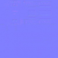
Normal Texture Example with no Alpha Channel (Parallax)
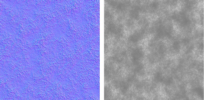
Normal Texture Example with Alpha Channel (Parallax)
Parameter
This texture is comprised of four separate channels which each form a separate data element. Linear color space (not sRGB) is used for these channels.
R: Emissive. This causes the texture to have an internal glow, even when no external light is present. Used for phosphors, permanently-lit markings, etc. The glow color is based on the albedo. Note that this glow does not cast light upon surrounding surfaces except via the Bloom post-processing effect.
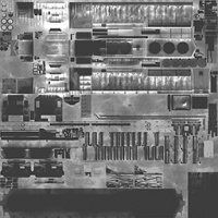
Parameters (Emissive - Red Channel) Texture Example
G: Roughness. Defines whether the surface reflections are shiny (0.0) or matte (1.0). See the PBR metal workflow for details.
Parameters (Roughness - Green Channel) Texture Example
B: Ambient Occlusion. Defines whether the surface is exposed to ambient lighting conditions (1.0) or affected only by direct lighting (0.0).
Parameters (Ambient Occlusion - Blue Channel) Texture Example
A: Metallicity. Defines whether the surface is metallic (1.0) with the albedo used to colorize reflected light, or dielectric (0.0) with the albedo used to colorize the surface. While intermediate values are not physically accurate, they may be used to emulate subsurfaces which are partially metallic. See the PBR metal workflow for details.
Parameters (Metallic - Alpha Channel) Texture Example
Material Attributes
The following attributes may be overridden in the mesh metadata file associated with the material's parent mesh:
- fadeInEndDistance - A single number (default 0.0) which defines the distance (in meters) at which the material will complete its fade in. If set to zero (default), no fade-in effect occurs and the material remains visible to zero distance. Fade-in begins at 75% of this distance and is complete by 100% of this distance. Fade-in occurs per fragment and is computed on the GPU so does not suffer any update lag when the object changes distances relative to the camera.
- fadeOutEndDistance - A single number (default 200.0) which defines the distance (in meters) at which the material will complete its fade out. This number should be at least 33% greater than the fadeInEndDistance. Fade-out begins at 75% of this distance and is complete by 100% of this distance. Fade-out occurs per fragment and is computed on the GPU so does not suffer any update lag when the object changes distances relative to the camera.
Please note that there is no performance benefit to a fragment being faded out- the GPU is still required to render each polygon and each fragment touched, even if it is fully faded. In practice, this can also increase the amount of overdraw in the scene, so a fully faded-out fragment may have more performance impact than a fully faded-in fragment.
Examples
TBD
3ds Max Material Configuration
Texture Assignment
TBD
Blender Material Configuration
TBD
