HowTo/Build Procedural Track for T:ANE
Tonyhilliam (Talk | contribs) |
Tonyhilliam (Talk | contribs) |
||
| Line 7: | Line 7: | ||
The ballast spline is the parent or base asset to which the other components are attached using the attached-splines container. Endcaps for the other components can be combined into a single mesh in the parent asset. When converting from a KIND Track asset the existing track-lod-tree can be retained for the ballast spline. | The ballast spline is the parent or base asset to which the other components are attached using the attached-splines container. Endcaps for the other components can be combined into a single mesh in the parent asset. When converting from a KIND Track asset the existing track-lod-tree can be retained for the ballast spline. | ||
| − | The correct position of the mesh relative to the origin in the 3D modeling environment. Spline rendering starts at the origin and proceeds along the -Y axis: | + | <i>The correct position of the mesh relative to the origin in the 3D modeling environment. Spline rendering starts at the origin and proceeds along the -Y axis:</i> |
[[File:PT_img1.png|300px|left]]{{clear}} | [[File:PT_img1.png|300px|left]]{{clear}} | ||
| − | |||
| − | |||
| + | <i>Basic configuration of the Ballast asset is as follows:</i> | ||
| + | <nowiki> | ||
kind "procedural-track" | kind "procedural-track" | ||
istrack 1 | istrack 1 | ||
trainz-build 3.9 | trainz-build 3.9 | ||
track-type "ballast" | track-type "ballast" | ||
| − | + | </nowiki> | |
| − | The attached splines container is configured as follows: | + | <i>The attached splines container is configured as follows:</i> |
| − | + | <nowiki> | |
attached-splines | attached-splines | ||
{ | { | ||
| Line 78: | Line 78: | ||
The sleeper spline is a child of the ballast spline, attached using the attached-splines container in the ballast spline. The spline consists only of 3D sleepers. Meshes can be culled as desired at lower lods simply by specifying no mesh at the low-detail node of the track-lod-tree. To preserve the correct spacing at the desired mesh length some additional tags are available. | The sleeper spline is a child of the ballast spline, attached using the attached-splines container in the ballast spline. The spline consists only of 3D sleepers. Meshes can be culled as desired at lower lods simply by specifying no mesh at the low-detail node of the track-lod-tree. To preserve the correct spacing at the desired mesh length some additional tags are available. | ||
| + | |||
| + | <i>Basic configuration of the Sleeper asset is as follows:</i> | ||
<nowiki> | <nowiki> | ||
| − | |||
| − | |||
kind "procedural-track" | kind "procedural-track" | ||
istrack 0 | istrack 0 | ||
| Line 87: | Line 87: | ||
</nowiki> | </nowiki> | ||
| − | The mesh-table for the sleeper asset includes a single sleeper instance which is used by the procedural junction system. The sleeper_single mesh is not referenced through the track-lod-tree. The term sleeper_single is specifically required in the mesh-table, the mesh file itself can be named as desired. The sleeper_single mesh is always used under junctions, the track-lod-tree is always used when not inside a junction. For this reason, we recommend you provide different lengths of spline section in the track-lod-tree, including down to a single sleeper length. | + | The mesh-table for the sleeper asset includes a single sleeper instance which is used by the procedural junction system. The sleeper_single mesh is not referenced through the track-lod-tree. The term <b>sleeper_single</b> is specifically required in the mesh-table, the mesh file itself can be named as desired. The sleeper_single mesh is always used under junctions, the track-lod-tree is always used when not inside a junction. For this reason, we recommend you provide different lengths of spline section in the track-lod-tree, including down to a single sleeper length. |
We do not currently support LOD on the sleeper_single mesh. This is planned in future. Do not use a .lm.txt file - this will stop the track from stitching, and make it slower. | We do not currently support LOD on the sleeper_single mesh. This is planned in future. Do not use a .lm.txt file - this will stop the track from stitching, and make it slower. | ||
| Line 119: | Line 119: | ||
<b>fig.c </b>- the position as adjusted in the spline’s track container for correct sleeper spacing.<br> | <b>fig.c </b>- the position as adjusted in the spline’s track container for correct sleeper spacing.<br> | ||
[[File:PT img2.png]]<br> | [[File:PT img2.png]]<br> | ||
| − | Note the use of the tags spacing-length-before and spacing-length-after in the track container below. Note also that no mesh has been specified at the lowest detail node in the track-lod-tree. This can be used to transition from 3D sleepers to 2D sleepers that are simply textured on to the ballast spline. | + | Note the use of the tags <b>spacing-length-before</b> and <b>spacing-length-after</b> in the track container below. Note also that no mesh has been specified at the lowest detail node in the track-lod-tree. This can be used to transition from 3D sleepers to 2D sleepers that are simply textured on to the ballast spline. |
<nowiki> | <nowiki> | ||
| Line 152: | Line 152: | ||
} | } | ||
</nowiki> | </nowiki> | ||
| − | [[File:PT | + | [[File:PT img3a.png]]<br> |
| − | The tag sleeper-pitch determines the spacing of single sleepers at junctions. It is measured from the centre of a sleeper to the centre of the next sleeper. | + | |
| + | The tag <b>sleeper-pitch</b> determines the spacing of single sleepers at junctions. It is measured from the centre of a sleeper to the centre of the next sleeper. | ||
The sleeper-pitch is only used for the junctions. It is not relevant for plain line tracks. | The sleeper-pitch is only used for the junctions. It is not relevant for plain line tracks. | ||
| − | |||
| − | |||
| + | <i>The privileges container is used to prevent the asset from being displayed in the Surveyor asset picker:</i> | ||
| + | <nowiki> | ||
privileges | privileges | ||
{ | { | ||
| Line 165: | Line 166: | ||
</nowiki> | </nowiki> | ||
| − | Chairs-left / Chairs-right (Plates) | + | ==Chairs-left / Chairs-right (Plates)== |
| − | Separate left and right splines for rail chairs or baseplates are children of the ballast spline, attached and laterally offset using the attached-splines container in the ballast spline. These splines consist only of 3D chairs. Configuration is similar to the sleepers spline above in that meshes can be culled as desired at lower lods; and the correct spacing between repeats is achieved using the tags spacing-length-before and spacing-length-after in the asset’s track container. This will also ensure that chairs and sleepers are correctly aligned. | + | Separate left and right splines for rail chairs or baseplates are children of the ballast spline, attached and laterally offset using the attached-splines container in the ballast spline. These splines consist only of 3D chairs. Configuration is similar to the sleepers spline above in that meshes can be culled as desired at lower lods; and the correct spacing between repeats is achieved using the tags <b>spacing-length-before</b> and <b>spacing-length-after</b> in the asset’s track container. This will also ensure that chairs and sleepers are correctly aligned. |
<b>fig.e </b>- the correct position of the mesh relative to the origin in the 3D modeling environment.<br> | <b>fig.e </b>- the correct position of the mesh relative to the origin in the 3D modeling environment.<br> | ||
<b>fig.f </b> - the position as adjusted in the spline’s track container for correct chair spacing.<br> | <b>fig.f </b> - the position as adjusted in the spline’s track container for correct chair spacing.<br> | ||
| + | [[File:PT img3.png]] <br> | ||
| + | |||
| + | |||
| + | |||
| + | <i>Basic configuration of the Chairs-left asset is as follows:</i> | ||
| + | <nowiki> | ||
| + | kind "procedural-track" | ||
| + | istrack 0 | ||
| + | trainz-build 3.9 | ||
| + | track-type "chairs-left" | ||
| + | </nowiki> | ||
| + | |||
| + | <i>Basic configuration of the Chairs-right asset is as follows:</i> | ||
| + | <nowiki> | ||
| + | kind "procedural-track" | ||
| + | istrack 0 | ||
| + | trainz-build 3.9 | ||
| + | track-type "chairs-right" | ||
| + | |||
| + | </nowiki> | ||
| + | The mesh-tables for the chair assets include a single chair instance which is used by the procedural junction system where multiple rails are in close proximity to allow for precise control over angle and position. The single chair mesh is not referenced in the track-lod-tree. | ||
| + | |||
| + | The term <b>chair_single</b> is specifically required in the mesh-table, the mesh file itself can be named as desired. The chair_single is always and only used with the single_sleeper. | ||
| + | |||
| + | A slide-chair for supporting the turnout blade is also included in the mesh-table for each chair asset. This must have the same height as a regular chair. | ||
| + | |||
| + | The term <b>blade_slidechair</b> is specifically required in the mesh-table, the mesh file itself can be named as desired. | ||
| + | The blade_slidechair will be used in the future, but it can be provided now so the assets won’t need to be updated. The blade_slidechair is provided in the same format as the chair_single, and will attach to the stock rail. | ||
| + | |||
[[File:PT img4.png]]<br> | [[File:PT img4.png]]<br> | ||
| + | |||
| + | <nowiki> | ||
| + | mesh-table | ||
| + | { | ||
| + | chairs-left-lod0 | ||
| + | { | ||
| + | mesh-asset <kuid:523:19723520> | ||
| + | mesh "chairs_left_lod0.im" | ||
| + | } | ||
| + | |||
| + | chairs-left-lod1 | ||
| + | { | ||
| + | mesh-asset <kuid:523:19723520> | ||
| + | mesh "chairs_left_lod1.im" | ||
| + | } | ||
| + | |||
| + | chair_single | ||
| + | { | ||
| + | mesh-asset <kuid:523:19723520> | ||
| + | mesh "chair_left_single.im" | ||
| + | } | ||
| + | |||
| + | blade_slidechair | ||
| + | { | ||
| + | mesh-asset <kuid:523:19723520> | ||
| + | mesh "slidechair_left.im" | ||
| + | } | ||
| + | } | ||
| + | </nowiki> | ||
| + | |||
| + | <i>The privileges container is used to prevent the assets from being displayed in the Surveyor asset picker:</i> | ||
| + | <nowiki> | ||
| + | privileges | ||
| + | { | ||
| + | permit-listing 0 | ||
| + | } | ||
| + | </nowiki> | ||
| + | ==Rail-left / Rail-right== | ||
| + | |||
| + | Separate left and right splines for rails are children of the ballast spline, attached and laterally offset using the attached-splines container in the ballast spline. At the top LOD the geometry should be segmented at approximately 5cm intervals in the modeler to facilitate precise procedural truncation and bending where rails cross each other at junctions. Note that unlike sleepers and chairs, the same rail mesh is used both on plain line and in junctions. | ||
| + | |||
| + | <i>Basic configuration of the Rail-left asset is as follows:</i> | ||
| + | <nowiki> | ||
| + | kind "procedural-track" | ||
| + | istrack 0 | ||
| + | trainz-build 3.9 | ||
| + | track-type "rail-left" | ||
| + | </nowiki> | ||
| + | <i>Basic configuration of the Rail-right asset is as follows:</i> | ||
| + | <nowiki> | ||
| + | kind "procedural-track" | ||
| + | istrack 0 | ||
| + | trainz-build 3.9 | ||
| + | track-type "rail-right" | ||
| + | </nowiki> | ||
| + | The mesh-tables for the rail assets include the remaining components required to form the turnouts... | ||
| + | |||
| + | |||
| + | <i>We adhere to the following naming convention for the meshes:</i> | ||
| + | [[File:PT img5.png]]<br> | ||
| + | |||
| + | ==Check Rails== | ||
| + | |||
| + | The body of the check rail should be segmented at approximately 10cm intervals to allow for precise procedural bending. The term <b>checkrail</b> is specifically required in the mesh-table, the mesh file itself can be named as desired. | ||
| + | |||
| + | The correct position of the meshes relative to the origin in the 3D modeling environment: | ||
| + | [[File:PT img7.png]]<br> | ||
| + | |||
| + | ==Wing Rails== | ||
| + | As these are procedurally attached to the closure rails, the cross section should therefore be identical to that of the stock / running rails. The body of the wing rail should be segmented at approximately 10cm intervals to allow for precise procedural bending. The term <b>wingrail</b> is specifically required in the mesh-table, the file itself can be named as desired. | ||
| + | |||
| + | <i>The correct position of the meshes relative to the origin in the 3D modeling environment:</i> | ||
| + | |||
| + | [[File:PT img6.png]]<Br> | ||
| + | |||
| + | ==Blades== | ||
| + | As these are procedurally bent to the required curvature the blades should be modeled straight and segmented at least every 25cm. The length of the tapered section should be roughly 50% of the total blade length. The contour of the tapered edge should be free of any chamfer such that it will mate seamlessly with the stock rail. Note that custom stock rails are not currently supported. | ||
| + | |||
| + | Animation must be a simple rotation with a single bone positioned at the origin. In order to be adaptable to a range of junction angles, a rotation of 5° should be employed, clockwise for the right blade, anti-clockwise for the left. Other arrangements are not currently supported. A length of 150 frames is recommended. The animation will be partially played through in game according to the required angle. | ||
| + | |||
| + | The term <b>blade</b> is specifically required in the mesh-table, the mesh and animation files can be named as desired. | ||
| + | |||
| + | [[File:PT img8.png]]<Br> | ||
| + | |||
| + | Stretcher: Also known as a ‘tie bar’. Animation is required to be a simple translation of 0.5 metres along the positive X axis with a single bone positioned at the origin. Other arrangements are not currently supported. A length of 150 frames is recommended to match that of the blade animation. The animation will be partially played through in game according to the required distance. | ||
| + | |||
| + | The term blade_stretcher is specifically required in the mesh-table, the mesh and animation files can be named as desired. | ||
| + | |||
| + | <i>The correct position of the mesh relative to the origin in the 3D modeling environment:</i> | ||
| + | [[File:PT img9.png]]<Br> | ||
| + | |||
| + | <nowiki> | ||
| + | mesh-table | ||
| + | { | ||
| + | rail-left-lod0 | ||
| + | { | ||
| + | mesh-asset <kuid:523:19723520> | ||
| + | mesh "rail_left_lod0.im" | ||
| + | } | ||
| + | |||
| + | rail-left-lod1 | ||
| + | { | ||
| + | mesh-asset <kuid:523:19723520> | ||
| + | mesh "rail_left_lod1.im" | ||
| + | } | ||
| + | |||
| + | rail-left-lod2 | ||
| + | { | ||
| + | mesh-asset <kuid:523:19723520> | ||
| + | mesh "rail_left_lod2.im" | ||
| + | } | ||
| + | |||
| + | wingrail | ||
| + | { | ||
| + | mesh-asset <kuid:523:19723520> | ||
| + | mesh "wingrail_left.im" | ||
| + | } | ||
| + | |||
| + | checkrail | ||
| + | { | ||
| + | mesh-asset <kuid:523:19723520> | ||
| + | mesh "checkrail_left.im" | ||
| + | } | ||
| + | |||
| + | blade | ||
| + | { | ||
| + | mesh-asset <kuid:523:19723520> | ||
| + | mesh "blade_left.im" | ||
| + | anim "blade_left.kin" | ||
| + | } | ||
| + | |||
| + | blade_stretcher | ||
| + | { | ||
| + | mesh-asset <kuid:523:19723520> | ||
| + | mesh "stretcher.im" | ||
| + | anim "stretcher.kin" | ||
| + | } | ||
| + | } | ||
| + | </nowiki> | ||
| + | |||
| + | The privileges container is used to prevent the assets from being displayed in the Surveyor asset picker: | ||
| + | |||
| + | <nowiki> | ||
| + | privileges | ||
| + | { | ||
| + | permit-listing 0 | ||
| + | } | ||
| + | </nowiki> | ||
| + | |||
| + | Additional tags are available for specifying some critical dimensions of rail-left and rail-right components: | ||
| + | |||
| + | <b>check-gauge </b>- (TOP LEVEL SPLINE) This is the distance between the inside face of one running rail, and the outside face of the check rail positioned next to the other running rail.<br> | ||
| + | <b>sleepers-orientation</b> - (TOP LEVEL SPLINE) the way the unified sleepers at the junction are oriented by default (later, it will be possible to override this setting per junction in the interface). The possible values for this tag are “average” (average direction of the two tracks) or “straightest” (follow the direction of the straightest track). | ||
| + | <b>rail-width </b>- (RAIL SPLINE) Width over the head of the rail. see fig.n below<br> | ||
| + | <b>checkrail-body-length</b> - (RAIL SPLINE) Length of the ‘body’ section of the check rail. This is the straight part, not including the flared ends. see fig.g above<br> | ||
| + | <b>wingrail-body-length </b>- (RAIL SPLINE) Length of the ‘body’ section of the wing rail. This is the straight part, not including the flared end. see fig.i above<br> | ||
| + | <b>blade-smallest-width </b>- (RAIL SPLINE) Minimum width of the head of the blade rail. see fig.k above | ||
| + | <b>blade-taper-length </b>- (RAIL SPLINE) the length of the taper of the blade. see fig.k<br> | ||
| + | <b>sleeper-pitch </b>- (SLEEPERS SPLINE) Distance from the center of a sleeper to the next sleeper, see fig in the sleepers section. Note : this value is just used for the custom sleepers positioning as an indication, it may be scaled according to the tracks configuration.<br> | ||
| + | <b>track-gauge </b>- (TOP LEVEL SPLINE) Distance between the inner faces of the running rails. see fig.o below | ||
| + | It's the 'real railway' way of measuring this - and is done this way because the actual track gauge can, and does, vary, but this distance must not expand with a widened track gauge.<br> | ||
| + | |||
| + | Consequently, people will find this number published and discussed, but the actual dimension you want is not generally published.<br> | ||
| + | [[File:PT img10.png]]<Br> | ||
| + | [[File:PT img11.png]]<Br> | ||
Revision as of 12:01, 5 May 2015
Contents |
Track Asset Requirements for Procedural Junction Support
T:ANE introduces a new track component structure that can be configured to support automatic procedural modification wherever junctions are encountered. To enable this feature a track asset of KIND Procedural-track is required. Unlike KIND Track, the individual components are exported as separate assets, ideally derived from a single mesh library.
Ballast
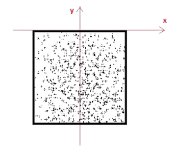
The ballast spline is the parent or base asset to which the other components are attached using the attached-splines container. Endcaps for the other components can be combined into a single mesh in the parent asset. When converting from a KIND Track asset the existing track-lod-tree can be retained for the ballast spline.
The correct position of the mesh relative to the origin in the 3D modeling environment. Spline rendering starts at the origin and proceeds along the -Y axis:
Basic configuration of the Ballast asset is as follows:
kind                                	"procedural-track"
istrack                             	1
trainz-build                        	3.9
track-type                          	"ballast"
The attached splines container is configured as follows:
attached-splines
{

  sleepers
  {
	lateral-offset                  	0
	use-same-direction              	1
	spline-kuid                     	<kuid:523:19723515>
	visual-only                     	1
  }

  chairs_left
  {
	lateral-offset                  	-0.751
	use-same-direction              	1
	spline-kuid                     	<kuid:523:19723516>
	visual-only                     	1
  }

  chairs_right
  {
	lateral-offset                  	0.751
	use-same-direction              	1
	spline-kuid                     	<kuid:523:19723517>
	visual-only                     	1
  }


 rails_left
  {
	lateral-offset                  	-0.751
	use-same-direction              	1
	spline-kuid                     	<kuid:523:19723518>
	visual-only                     	1
  }

  rails_right
  {
	lateral-offset                  	0.751
	use-same-direction              	1
	spline-kuid                     	<kuid:523:19723519>
	visual-only                     	1
  }
}
lateral-offset: defines the number of metres that the child spline is offset sideways from its parent's origin. Positive values offset to the right, and negative values offset to the left.
use-same-direction: causes the child spline to face in the same direction as the parent. (see on the wiki)
spline-kuid: unique identifier for the attached spline asset.
visual-only: Removes the functional aspects of the child spline, preventing for example, the ballast and the rail splines being treated as separate stretches of track. Also prevents undesired manual editing of the individual components in Surveyor.
Sleepers (Ties)
The sleeper spline is a child of the ballast spline, attached using the attached-splines container in the ballast spline. The spline consists only of 3D sleepers. Meshes can be culled as desired at lower lods simply by specifying no mesh at the low-detail node of the track-lod-tree. To preserve the correct spacing at the desired mesh length some additional tags are available.
Basic configuration of the Sleeper asset is as follows:
kind                                	"procedural-track"
istrack                             	0
trainz-build                        	3.9
track-type                          	"sleepers"
The mesh-table for the sleeper asset includes a single sleeper instance which is used by the procedural junction system. The sleeper_single mesh is not referenced through the track-lod-tree. The term sleeper_single is specifically required in the mesh-table, the mesh file itself can be named as desired. The sleeper_single mesh is always used under junctions, the track-lod-tree is always used when not inside a junction. For this reason, we recommend you provide different lengths of spline section in the track-lod-tree, including down to a single sleeper length.
We do not currently support LOD on the sleeper_single mesh. This is planned in future. Do not use a .lm.txt file - this will stop the track from stitching, and make it slower.
mesh-table
{
  sleepers-lod0
  {
	mesh-asset                      	<kuid:523:19723520>
	mesh                            	"sleepers_lod0.im"
  }

  sleepers-lod1
  {
	mesh-asset                      	<kuid:523:19723520>
	mesh                            	"sleepers_lod1.im"
  }

  sleeper_single
  {
	mesh-asset                      	<kuid:523:19723520>
	mesh                            	"sleeper_single.im"
  }
}
Some extra tags in the track container are used to set the desired position of the sleeper mesh...
fig.b - the correct position of the mesh relative to the origin in the 3D modeling environment.
fig.c - the position as adjusted in the spline’s track container for correct sleeper spacing.
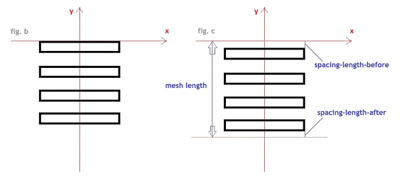
Note the use of the tags spacing-length-before and spacing-length-after in the track container below. Note also that no mesh has been specified at the lowest detail node in the track-lod-tree. This can be used to transition from 3D sleepers to 2D sleepers that are simply textured on to the ballast spline.
track
{
  mesh-length                       	                3
  spacing-length-before             	0.2
  spacing-length-after              	0.2

  track-lod-tree
  {
     lod-distance                    	              200

     high-detail
     {
         lod-distance                                 50

         high-detail
         {
            mesh                                        "track-lod0"
         }

         low-detail
         {
         mesh                        	               "track-lod1"
         }
     }

     low-detail
     {
     }
  }
The tag sleeper-pitch determines the spacing of single sleepers at junctions. It is measured from the centre of a sleeper to the centre of the next sleeper. The sleeper-pitch is only used for the junctions. It is not relevant for plain line tracks.
The privileges container is used to prevent the asset from being displayed in the Surveyor asset picker:
privileges
{
  permit-listing                    	0
}
Chairs-left / Chairs-right (Plates)
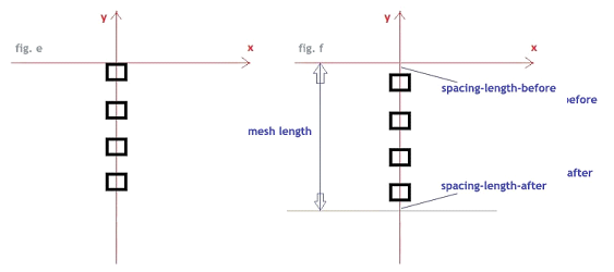
Separate left and right splines for rail chairs or baseplates are children of the ballast spline, attached and laterally offset using the attached-splines container in the ballast spline. These splines consist only of 3D chairs. Configuration is similar to the sleepers spline above in that meshes can be culled as desired at lower lods; and the correct spacing between repeats is achieved using the tags spacing-length-before and spacing-length-after in the asset’s track container. This will also ensure that chairs and sleepers are correctly aligned.
fig.e - the correct position of the mesh relative to the origin in the 3D modeling environment.
fig.f - the position as adjusted in the spline’s track container for correct chair spacing.
Basic configuration of the Chairs-left asset is as follows:
kind                                	"procedural-track"
istrack                             	0
trainz-build                        	3.9
track-type                          	"chairs-left"
Basic configuration of the Chairs-right asset is as follows:
kind                                	"procedural-track"
istrack                             	0
trainz-build                        	3.9
track-type                          	"chairs-right"
The mesh-tables for the chair assets include a single chair instance which is used by the procedural junction system where multiple rails are in close proximity to allow for precise control over angle and position. The single chair mesh is not referenced in the track-lod-tree.
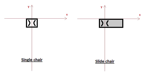
The term chair_single is specifically required in the mesh-table, the mesh file itself can be named as desired. The chair_single is always and only used with the single_sleeper.
A slide-chair for supporting the turnout blade is also included in the mesh-table for each chair asset. This must have the same height as a regular chair.
The term blade_slidechair is specifically required in the mesh-table, the mesh file itself can be named as desired. The blade_slidechair will be used in the future, but it can be provided now so the assets won’t need to be updated. The blade_slidechair is provided in the same format as the chair_single, and will attach to the stock rail.
mesh-table
{
  chairs-left-lod0
  {
	mesh-asset                      	<kuid:523:19723520>
	mesh                            	"chairs_left_lod0.im"
  }

   chairs-left-lod1
  {
	mesh-asset                      	<kuid:523:19723520>
	mesh                            	"chairs_left_lod1.im"
  }

 chair_single
  {
	mesh-asset                      	<kuid:523:19723520>
	mesh                            	"chair_left_single.im"
  }

 blade_slidechair
  {
	mesh-asset                      	<kuid:523:19723520>
	mesh                            	"slidechair_left.im"
  }
}
The privileges container is used to prevent the assets from being displayed in the Surveyor asset picker:
privileges
{
  permit-listing                    	0
}
Rail-left / Rail-right
Separate left and right splines for rails are children of the ballast spline, attached and laterally offset using the attached-splines container in the ballast spline. At the top LOD the geometry should be segmented at approximately 5cm intervals in the modeler to facilitate precise procedural truncation and bending where rails cross each other at junctions. Note that unlike sleepers and chairs, the same rail mesh is used both on plain line and in junctions.
Basic configuration of the Rail-left asset is as follows:
kind                                	"procedural-track"
istrack                             	0
trainz-build                        	3.9
track-type                          	"rail-left"
Basic configuration of the Rail-right asset is as follows:
kind                                	"procedural-track"
istrack                             	0
trainz-build                        	3.9
track-type                          	"rail-right"
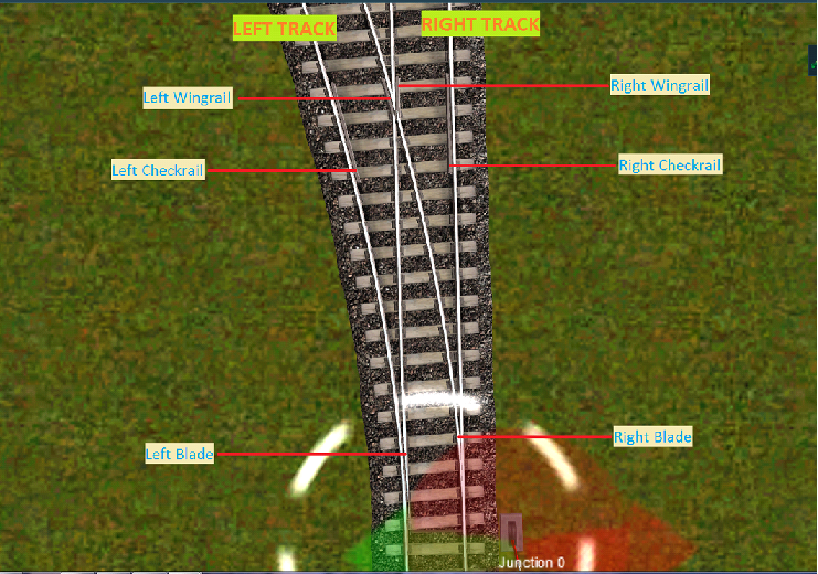
The mesh-tables for the rail assets include the remaining components required to form the turnouts...
We adhere to the following naming convention for the meshes:
Check Rails
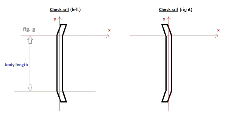
The body of the check rail should be segmented at approximately 10cm intervals to allow for precise procedural bending. The term checkrail is specifically required in the mesh-table, the mesh file itself can be named as desired.
The correct position of the meshes relative to the origin in the 3D modeling environment:
Wing Rails
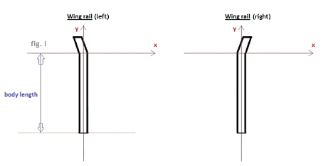
As these are procedurally attached to the closure rails, the cross section should therefore be identical to that of the stock / running rails. The body of the wing rail should be segmented at approximately 10cm intervals to allow for precise procedural bending. The term wingrail is specifically required in the mesh-table, the file itself can be named as desired.
The correct position of the meshes relative to the origin in the 3D modeling environment:
Blades
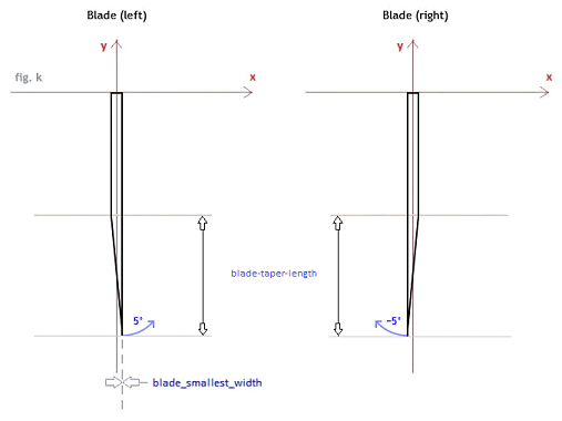
As these are procedurally bent to the required curvature the blades should be modeled straight and segmented at least every 25cm. The length of the tapered section should be roughly 50% of the total blade length. The contour of the tapered edge should be free of any chamfer such that it will mate seamlessly with the stock rail. Note that custom stock rails are not currently supported.
Animation must be a simple rotation with a single bone positioned at the origin. In order to be adaptable to a range of junction angles, a rotation of 5° should be employed, clockwise for the right blade, anti-clockwise for the left. Other arrangements are not currently supported. A length of 150 frames is recommended. The animation will be partially played through in game according to the required angle.
The term blade is specifically required in the mesh-table, the mesh and animation files can be named as desired.
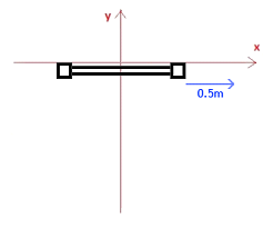
Stretcher: Also known as a ‘tie bar’. Animation is required to be a simple translation of 0.5 metres along the positive X axis with a single bone positioned at the origin. Other arrangements are not currently supported. A length of 150 frames is recommended to match that of the blade animation. The animation will be partially played through in game according to the required distance.
The term blade_stretcher is specifically required in the mesh-table, the mesh and animation files can be named as desired.
The correct position of the mesh relative to the origin in the 3D modeling environment:
mesh-table
{
  rail-left-lod0
  {
	mesh-asset                      	<kuid:523:19723520>
	mesh                            	"rail_left_lod0.im"
  }

  rail-left-lod1
  {
	mesh-asset                      	<kuid:523:19723520>
	mesh                            	"rail_left_lod1.im"
  }

  rail-left-lod2
  {
	mesh-asset                      	<kuid:523:19723520>
	mesh                            	"rail_left_lod2.im"
  }

  wingrail
  {
	mesh-asset                      	<kuid:523:19723520>
	mesh                            	"wingrail_left.im"
  }

  checkrail
  {
	mesh-asset                      	<kuid:523:19723520>
	mesh                            	"checkrail_left.im"
  }

  blade
  {
	mesh-asset                      	<kuid:523:19723520>
	mesh                            	"blade_left.im"
	anim                            	"blade_left.kin"
  }

  blade_stretcher
  {
	mesh-asset                      	<kuid:523:19723520>
	mesh                            	"stretcher.im"
	anim                            	"stretcher.kin"
  }
}
The privileges container is used to prevent the assets from being displayed in the Surveyor asset picker:
privileges
{
  permit-listing                    	0
}
Additional tags are available for specifying some critical dimensions of rail-left and rail-right components:
check-gauge - (TOP LEVEL SPLINE) This is the distance between the inside face of one running rail, and the outside face of the check rail positioned next to the other running rail.
sleepers-orientation - (TOP LEVEL SPLINE) the way the unified sleepers at the junction are oriented by default (later, it will be possible to override this setting per junction in the interface). The possible values for this tag are “average” (average direction of the two tracks) or “straightest” (follow the direction of the straightest track).
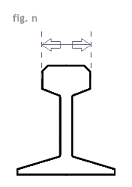
rail-width - (RAIL SPLINE) Width over the head of the rail. see fig.n below
checkrail-body-length - (RAIL SPLINE) Length of the ‘body’ section of the check rail. This is the straight part, not including the flared ends. see fig.g above
wingrail-body-length - (RAIL SPLINE) Length of the ‘body’ section of the wing rail. This is the straight part, not including the flared end. see fig.i above
blade-smallest-width - (RAIL SPLINE) Minimum width of the head of the blade rail. see fig.k above
blade-taper-length - (RAIL SPLINE) the length of the taper of the blade. see fig.k
sleeper-pitch - (SLEEPERS SPLINE) Distance from the center of a sleeper to the next sleeper, see fig in the sleepers section. Note : this value is just used for the custom sleepers positioning as an indication, it may be scaled according to the tracks configuration.
track-gauge - (TOP LEVEL SPLINE) Distance between the inner faces of the running rails. see fig.o below
It's the 'real railway' way of measuring this - and is done this way because the actual track gauge can, and does, vary, but this distance must not expand with a widened track gauge.
Consequently, people will find this number published and discussed, but the actual dimension you want is not generally published.
