Junction Kit Configuration
Contents |
Notes on the Assets
Default Control
By default clicking on a fixed track junction asset will only toggle the first referenced switch, usually item 0 in the junction-vertices table. There is no way that the other nodes can be manually switched without script. However the AI will be able to successfully negotiate the object no matter how many junction-vertices are defined.
The assets do not respond to the junction-direction button on the track tab in Surveyor and they cannot be switched on the minimap.
These drawbacks can only be addressed by Auran.
Script Library Control
There is a button in the Properties dialogue which allows you to toggle through all of the possible settings for each asset. This sets a new default for the session which is remembered across session saves.
In Driver the AI is left to its own devices and should be able to switch the junctions properly without interference from the script. Compound objects such as slips, crossovers and diamonds include mutexes which prevent the game from granting simultaneous permits for conflicting routes across the assets. The script will monitor trains crossing these objects and will derail both trains if a collision is detected.
Pressing J or ^J from a train will toggle the node nearest to the train and will set up any other junction nodes to suit.
Clicking on the mesh will toggle to the next available state.
It is not possible to detect the difference between a mouse click on the mesh and a keypress from a train approaching the first node with 100% accuracy.
Levers
Levers are entirely decorative, the junctions are activated by a click on the main mesh. See Junction Lever Configuration for notes on creating these objects.
Junction Linking
Links are ignored by the AI - they only operate when the junctions are manually switched.
Asset Configuration
config.txt: Tags & Containers
- This is a list of tags and containers which relate to fixed track junctions.
- Tags in bold type are essential for correct operation of the Library.
- You will also need a mesh-table, junction-vertices and attached -track containers.
| Tag | Value | Description |
| kind | fixedtrack | This is mandatory, fixed junctions will not work as any other asset kind. |
| use-named-track | 1 | This tag enables messages to be generated for scenery triggers attached to the junctions |
| use-gradient-track | 1 | This affects the way that TRS handles height adjustments. |
| rotate-yz-range | -10,10 | Allows junctions to be rolled to align with a grade. This is optional but if you wish to implement it you will need to align your models along the X axis in GMax, horizontally on the 'page' |
| rollstep | 0.1 | Defines the minimum angular increment when junctions are rolled. |
| script-include-table { 0 } |
<kuid:122285:79000> |
This is a pointer to the asset containing the script referenced by JKObject.gs. |
| script | "JKObject" | The script file which you should drop into your asset folder |
| class | "JKObject" | The name of the script class within this file |
| kuid-table { codelib |
<kuid:122285:79000> |
codelib is the script library. |
| extensions { jk2-122285 { |
|
junction-type (see below) defines the layout and behaviour of the junction. default-state (see below) defines the initial state of the junction when first placed in Surveyor, this defaults to 0 and can be altered in Surveyor. |
junction-type codes
- A correct entry for this tag in the extensions table is essential for the script to recognise what actions need to be taken in response to conditions encountered.
- The sub-table should remain as jk2-122285, do not alter it to your own kuid.
| Value | Description |
| -3 | Placeholder used by the script to reference 3 way spline junctions |
| -2 | Placeholder used by the script to reference 2 way spline junctions |
| -1 | Generic clickable object such as Signal Box Asset |
| 0 | Fixed track object with no animations, typically this would be a spacer which has no animations but which which needs scripted ability (such as ballast hiding) to match other assets. |
| 1 | Diamond crossing |
| 2 | Catch point (Derail) |
| 3 | Two way point |
| 4 | Three way point |
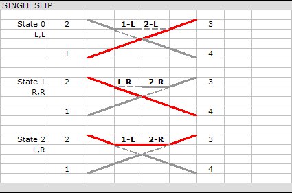
| 5 | Single slip |
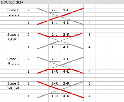
| 6 | Double slip |
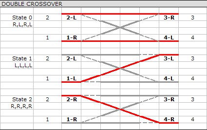
| 7 | Double crossover |
| 8 | Single Crossover (UK Trailing) |
| 9 | Single Crossover (UK Leading) |
| Other types may be defined and added to this list as the project progresses. |
default-state codes
- These are not always the same as the junction direction constants defined in TRS.
- For multi junction objects, to allow the script to understand which node is which they must be defined in config.txt in the same order as set out in the diagrams below.
mesh table containers
- The library deals with animations and hiding of meshes based on the mesh names.
- The actual content of the mesh containers is of no relevance to the script except where noted below.
- The following special names are recognised.
- Additional special mesh names will be added as the project develops.
| Mesh Name | Script Action |
| template# | These are marker meshes which can be used for alignment or simply to indicate the location of node 1. You can provide any number of thesem starting with template1, template2,...,templaten. As long as there are no breaks in the numeric sequence each mesh will be displayed or hidden as appropriate. These meshes are only ever visible in Surveyor. |
| blade# | These should contain mesh and animation references. Use blade1 for meshes attached to the first node and so on. The library supports both *.im and *.lm meshes. |
| ballast# | If meshes named ballast are supplied they can be hidden via a property object option. Again you can serialise the containers to have the script act on more than one mesh. |


