HowTo/Use Superelevation
Contents |
Superelevation : a new feature
The "superelevation" or the slope of rails in curves is proposed from now on in T:ANE.
Here is the example of a machine launched to 80 kph in a curve of 500 meters of beam. The slope of the track has to be 4 ° to resist the centrifugal force and not to wear out prematurely the outer rails.
However, the implementation of the superelevation in T:ANE is little transparent for the moment. Here is thus a small guide that will supply you all the necessary elements.
In T:ANE, the superelevation is adjusted by means of two parameters. We reach them by the panel "track", and "advanced"

 By clicking on a summit of a track spline, we reveal both parameters to be served. These two parameters are thereafter referred as p1 and p2.
Superelevation : short definition
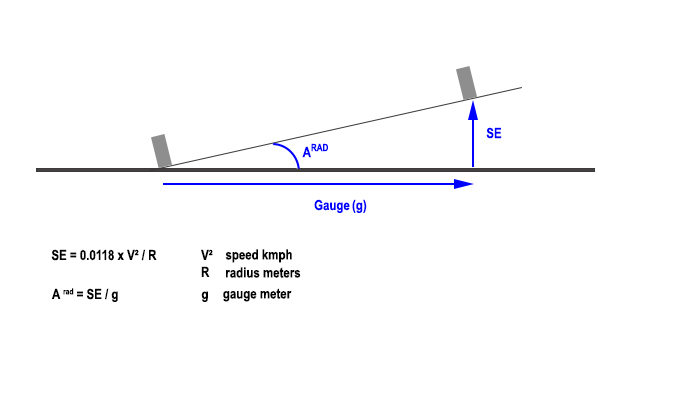
The Superelevation is the height that the outside rail takes compared with the internal rail in a curve.
It is calculated as the plan below shows it:
If, to calculate the superelevation, the beam of the curve is unknown, it can be calculated by measuring the arrow and the chord of the curve:
Every country has its own standards of superelevation. We find them rather easily on the internet.
In France, the superelevation does not have to exceed 16 cms (6.3 inches) in standard gauge way and 10 cms (3.94 inches) in metrics.
Mode of calculation in T:ANE
To proceed to the calculations, download the spreadsheet GGG
In the left column, seize the minimum radius of curvature that can know your network, a maxi speed and choose the gauge (standard or metric).
Observe the calculated parameter of Superelevation (SE). If it exceeds 6.3 inch in standard gauge or 3.94 in metrics, it is necessary to decrease the maxi speed (according to French standards).
The parameters p1 and p2 then obtained can apply to all the curves of your network, whathever is their radius of curvature, since the maxi speed will not exceed the one that you seized in the spreadsheet.
An example:
In the spreadsheet, you seize the values beam = 150 ft, speed = 55 mph and standard gauge. And you obtain a superelevation = 5 inches , p1 = 43.73 and p2 = 0.089 radians.
You put a track with these parameters and you make vary the beam of the curve:
- If the beam is 150 ft, the superelevation will be 5 inches and the angle of inclination of the way of 0.089 radians
- If the beam is 300 ft, the superelevation will be 2.5 inches and the angle of inclination of the way of 0.044 radians
- If the beam is 75 ft, the superelevation will be 10 inches and the angle of inclination of the way of 0.178 radians.
If the speed of your trains does not exceed 55 mph, the installation is correct. Except that in this example and for a 75 ft beam, the superelevation exceeds the authorized 6.3 inches. By means of the spreadsheet, look for the maxi speed which, for a 75 ft beam, allows to respect a maxi superelevation of 6.3 inches. Apply the new parameters p1 and p2 to your curve.
Other points to be respected:
- There is no superelevation for speeds lower than 15.5 mph in standard gauge and 18.5 mph in metrics (French standards, 25 kmph and 30 kmph)
- On networks with gauge of 2 ft or less, the speed is limited to 15.5 mph (25 kph) : there is thus no superelevation either.
On the spreadsheet, the right column allows you to calculate p1 and p2 from the values of chord and arrow of a curve.
Methodology
Formulaes used on the spreadsheet are two orders:
- the calculation of the beam of a curve from the measure of its arrow and its chord
- the calculation of the superelevation and the angle formed by the track
are formulaes of physics which we can be easily found in diverse books or web sites.
Formulaes allowing to calculate p1 and p2 in T:ANE are personal extrapolations, having identified that the parameter p1 is proportional in the square of the maxi speed in standard gauge.
I was then able to build a model according to the graph below:
The calculations were the object of test directly on a map.
Screenshot pasted in Photoshop and drawing of a red line on the front of the machine : Photoshop indicates the angle of the line (here 4,2 °).
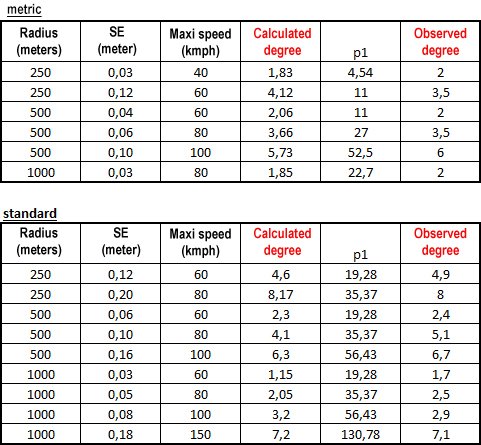
To estimate the robustness of the model, I proceeded to a series of tests with diverse curves, speeds and gauges. I then compared the value of calculated angles with the value of observed angles. By keeping in mind that a gap from some tenth of degree is of course imperceptible in the eye.
The coefficient of correlation between both series of degrees is: r² = 0.983. Q.E.D.


