Help:Surveyor Objects Tools
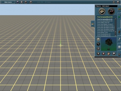
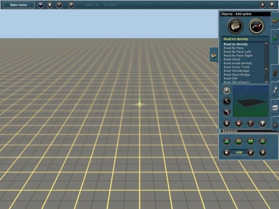
Objects (F3) tab in Surveyor allows you to place two different types of objects - objects and splines. "Object" scenery items are single structures such as buildings and trees. "Spline" objects are repeatable and can be stretched over a distance. These includes items such as roads, fences and powerlines.
Open the Objects Menu by clicking on the Objects Tab (F3) and choose the Objects or Spline Tab at the top.
Contents |
Objects
The default mode is Objects.
 Object selection
Scroll through the list of objects by clicking on the up and down arrows at the right of the list. The selected object shows as a rotating 3D object in the viewer window.
 Add Object
Check that you are in Add Object mode, or Click LMB on Add Object (A) to select this mode. Click LMB on the terrain and the selected object is placed wherever you click. You can repeat this several times quickly adding a number of trees or buildings.
 Move Object
Click on the Move Object (M) and Click LMB+H on any object and then drag the object around the terrain to new positions.
 Rotate Object
Click on the Rotate Object (R) and Click LMB+H and move the mouse left and right to rotate the objects. A display shows you the number of degrees of rotation. You can set objects to “randomly rotate” or not by choosing the Randomly Rotate option in the Surveyor Options menu from the Main Menu.
 Get Object
Click on the Get Object (G) tool and then Click LMB on an object already placed on the terrain. The object selected now appears in the selection window. Change the mode to Add Object (A) and Click LMB again on the terrain where you wish to place another copy of the newly selected object.
 Delete Object
Select Delete Object (D) then Click LMB to delete an object. Continue Clicking LMB to delete a number of objects. If you click on the wrong object, click on Undo (Ctrl-Z) to undo the last action and replace the last deleted object.
 Height Adjust
Click LMB on Height Adjust (H) to enable the adjustment of the height of any Object. Only objects which have been designed to be height adjustable will allow you to adjust their height. S Holding the Ctrl key in conjunction with this move will adjust the object’s height in increments of 0.1 units and holding the Shift key will change the height by units of 0.05.
 Edit Properties
Click LMB on Edit Properties (N). Then Click LMB on any object in your route. A menu will then open up allowing you to edit the properties of the object.
Spline
This tab provides tools that are used to manipulate scenery spline objects. The Spline Mode (S) button is at the top right of the Objects (F3) tab.
Splines are generally long thin objects such as roads, power lines, catenaries, fences, terrace houses and rows of trees. They consist of two or more “spline points” denoted by rotating circles. These spline points can be placed any distance apart and the spline object is then stretched and duplicated as needed between the spline points.
Spline objects can be constructed with different features to accommodate the variety of objects that can be modelled as splines.
 Add Spline
Select the Add Spline (A) tool and then click LMB on the terrain to anchor the first spline point. Click LMB again some distance away to place the second spline point. The spline will be drawn from the first point to the second, and white circles will display at each of the spline points. These spline points are used to configure the spline path, adjust the height, or define a section of spline for operations such as setting a gradient or setting the ground height.
To extend the spline further, click LMB on the last spline point, then Click LMB once more nearby to extend the spline. To place multiple spline points hold down the Ctrl key while placing each point. Release the Ctrl key before placing the final spline point to complete the spline. Additional sections can be added to an existing spline at any time.
If the new spline point (including an end point) is placed close to any part of an existing compatible spline the new point will form a junction with the existing spline. If this is not what is required, press and hold the Shift key before releasing the LMB.
 Move Spline
Select the Move Spline (M) tool and then click LMBH and drag the spline point to a new position.
If the new position is close to an existing spline point of a compatible spline, the spline point you are moving will snap to that other spline point, creating either a junction or an extension. In some cases this is not what is required: to prevent this from happening, press and hold the Shift key before releasing the LMB. This technique can be used to place separate splines on top of one another, such as when creating a forest from tree or shrub splines.
 Split Spline
Select the Split Spline (Q) tool and then click LMB on a spline point (other than an end point) to split the spline at that point. Two end spline points will be created at the same location, and the two portions of the spline will become separate splines.
 Get Spline
Select the Get Spline (G) tool and then click LMB on a spline object already placed on the terrain. That spline object will become the selected object in the objects list, and the Add Spline (A) tool will become the active tool.
Get to Pick List
To access the Get to Pick List function, Right Click on the Get button, and the icon will then change to the Get to Pick List button. Now Left Click this button to select the Get to Pick List tool.
The Get to Pick List tool allows you to 'get' any object on a route, and then add it to a Pick List. The Pick List that the item is added to is the current Pick List in the Content Search Filter window: be sure that the correct Pick List is the current Pick List before selecting the spline object with the Get to Pick List Tool.
 Delete Spline
Select the Delete Spline (D) tool then click LMB on a section of spline between two spline points to delete that section of spline. The remaining portions will become separate splines.
 Straighten Spline
Select the Straighten Spline tool (B) then click LMB on a section of spline to straighten that section. The curvature of adjacent sections will be adjusted to maintain a smooth spline path, but spline points will not be moved. Click LMB on a straightened section of spline to remove the straightening.
Note that the exact effect of straightening a section depends on the properties of the spline object and whether adjacent sections have already been straightened. For instance, two adjacent sections cannot be straightened if the spline points that define them are not in a straight line.
 Toggle Traffic
Many roads will have vehicles travelling on them automatically: this can be seen while in Surveyor after placing the roads. Clicking LMB on Toggle Traffic turns all traffic off on the roads. Clicking LMB on the button again will have traffic resume. When toggling traffic on and off, it affects all spline roads on your route.
In some versions of Trainz this option is in the Environment - Location panel of the Surveyor Main Menu.
 Edit Properties
Select the Edit Properties (P) tool and then click LMB on any spline object in your route. A menu will open up allowing you to edit the properties of the object.
Advanced
Click LMB on the Advanced Menu to access the advanced spline tools.
 Spline Height
Select the Spline Height (H) tool and then LMBH and drag on a spline point to raise or lower that point. The adjacent sections of the spline will be adjusted to the new height according to the properties of the spline. The rotating circle marking the spline point will be changed from white to yellow, indicating that the height is now absolute, not relative to the local ground level. Note that the spline point height will become an absolute height even if the height doesn't actually change.
The height of the spline point will be displayed as it is adjusted. Press and hold the Ctrl key to adjust the height in smaller increments.
 Delete Spline Point
Select the Delete Spline Point (X) tool and then click LMB on a spline point to delete that point. The two adjacent segments will become a single segment, and the spline path will be adjusted. You cannot delete an end spline point but you can delete an end section using the Delete Spline (D) tool. You cannot delete a spline point that is a junction.
 Insert Spline Point
Select the Insert Spline Point (I) tool then click LMB between two existing spline points. A new spline point will be created at the click location, and the spline path will be adjusted. The height of the new spline point will be calculated from the slope of the existing section. If the section had been straightened it may be necessary to re-do the straightening.
 Smooth Spline
Select the Smooth Spline (S) tool then click LMB on a section of spline to adjust the ground level to the height of the spline. Multiple clicks (up to about 6) will increase the smoothness of the adjacent terrain.
 Get Vertex Height
Select the Get Vertex Height tool and Click LMB on a spline point. The height of that spline point will be displayed in the Height Value box.
 Edit Vertex Height
As an alternative to the Get Vertex Height tool to select a Height Value, you can enter a specific height in the Height Value Field.
 Apply Vertex Height
Select the Apply Vertex Height tool then Click LMB on a spline point. The height of the spline point is adjusted to the height displayed in the Height Value text box.
 Remove Gradient
Select the Remove Gradient tool and then Click LMB on a spline point to reset the height of the spline.
When a spline point is first added its height is zero relative to the ground at the point at which it is located, and its height follows any changes in the ground height. This is indicated by a white rotating circle. If the height is adjusted it becomes an absolute height, so that the height does not change with subsequent changes in ground height, and this is indicated by a yellow rotating circle. The Remove Gradient tool reverts the spline point height to its original state - zero relative to the ground and a white rotating circle. This change also restores some properties of certain splines - if the spline has been configured to follow the height and/or slope of the ground surface between spline points then this feature is restored to a spline section when the adjacent spline points are changed from absolute height to relative height.
If a spline point height is already zero relative to the ground (white rotating circle) then this tool has no effect.
- See Also

