Help:Surveyor Track Tools
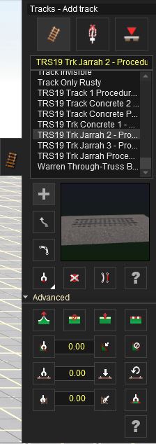
Tracks (F4) allows you to place tracks on the baseboard. Select a suitable track type from the Track Tab Window, then move over to the baseboard and place (LMB).
Track sections in TS12 are made up of flexible length track pieces created by placing 2 spline points. It is called “flexi-track” and it makes laying any lengths of track extremely simple. Select the Track Menu (F4) and the default selection will be Track Mode (T).
Track mode
 Track selection
To choose a track use the arrows pointing up and down to the right of the list to navigate it. Click LMB on a name and it will show the model on the screen below. Alternatively write the name of the particular track on the textbox over the list.
 Add Track
Click on the Add Track (A) tool and then Click on the left or right arrows of the track selection dialogue to select the type of track you wish to lay, then Click LMB on the baseboard where you want to anchor your starting point. Click LMB again a short distance away to place another spline point. To extend the track further, Click LMB again on the last spline point (the white circle), then Click LMB once more nearby to extend the track. Unless all three spline points are exactly in a straight line, the track will be curved. To connect two sections of track, drag the end spline point of one on top of the end spline point of another and they will automatically connect.
 Move Track
To bend the track in any direction, select the Move Track (M) tool and then Click LMB and hold on one of the white spline point circles and drag it so it'll bend. The shape of the curve is affected by how close the spline point you are pulling is to the next spline points.
 Split Spline
Click on the Split Spline tool (Q) and click on a middle spline point (white circle) in the track. The track breaks in two at that point.
 Get Track
Click on Get Track (G) and then Click LMB on a track. Its image will appear on the Selection Window. Press “A” to change the mode to Add Track and you will be able to lay the same one.
Right clicking the Get Track button will toggle to or from the Get to Pick List function.
The Get to Picklist tool allows you to 'get' any object on a route, and then add it to a Pick List automatically.
 Delete Track
Click on Delete Track (D) then click on the bridge section to delete it. If there are any objects on the track, they will also be deleted.
 Straighten Track
Click on Straighten Track (B) and then Click LMB on a bent section of laid track. The section of track will straight between the two spline points, the next track segment will also affected (Double track cannot be straightened. Click again on the straightened track and it will return to a curved track.
 Edit properties
This can be used to name the track section, set its layer, and modify the Track Condition.
Advanced
Click LMB on the Advanced button(Shift F4) to drop down the Advanced Track Menu.
 Spline Height
Click LMB the Adjust Spline Height (H) and Click LMB and hold on a track spline point. Drag your mouse forward and back to raise and lower the spline point.
 Delete Spline Point
Click LMB on the Delete Spline Point (X) and Click LMB on a track spline point . When a spline is removed the curvature of a track can be affected.
 Insert Spline Point
Click on Insert Spline Point (I) to add a new spline point.
 Smooth Spline
Smooth Spline (S) levels the track between two spline points, bringing the land up or down to match the leveled track.
 Get Gradient
Click Get Gradient (J) and Click LMB on a raised track section between two track spline points. The gradient between those points is shown in the Gradient Value box as a percentage slope.
 Apply Gradient
Enter a new gradient value in the Gradient Value text box, then click on Apply Gradient (K).
 Get Track Condition
Click the Get Track Condition button, then Click LMB on a section of track to get the current Track Condition.
 Track Condition Value
Shows the Track Condition obtained from the Get Track Condition button. You can manually enter a Track Condition value (between 0 and 1), and then use the Apply Track Condition tool to apply the Track Condition to the track splines.
 Track Condition Apply
Applies the track condition shown in the Track Condition Value box.
See Track Condition for further information.
 Track Condition Default
Resets the track condition to the track spline's default value (generally 50%).
 Remove Gradient
Click LMB on remove Gradient and then Click on a track section to remove the gradient between two track points.
 Get Vertex Height
Click LMB on the Get Vertex Height and Click LMB on the highest spline point on your track. The height is displayed in the Height Value box.
 Get Vertex Height
Shows the Vertex Height obtained from the Get Vertex Height tool. You can manually enter a Vertex Height value (between 0 and 1), and then use the Vertex Height Apply tool to apply the Vertex Height to the track vertex (spline point).
 Apply Vertex Height
Click on Apply Vertex Height then Click LMB on another spline point. The spline point is raised to the same height as you first vertex.
 Show Curve Radius
Click on Show Curve Radius then move your mouse along a track segment. The curve radius is shown next to your mouse cursor. The number is the radius measured in meters so a low number means a tight curve and a high number means a straighter track.
 Track Vertex Properties
The Track Vertex Properties allows you to access the properties for each track vertex (spline point). To use this tool, select the Track Vertex Properties tool, then click on a Track Vertex (Spline Point).
Currently, the Track Vertex Properties are used to configure the Superelevation of track on curves.
Trackside Mode
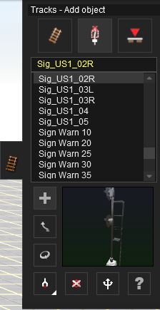
The second mode in the Track Menu is Trackside Mode. Click LMB on Trackside Mode (Y) to change the Track Tab menu to the Trackside Mode menu.
 Add Object
To add a trackside object Click LMB on the Add Object (A) button. The select the object you wish to place from the list. Click LMB at one or the other side at some point of the track. Your object will be placed beside the track and will be “attached” to it. So if you move the track it will move with it.
 Move Object
Click LMB on Move Object (M). Then Click LMB+H on a Trackside Object on your track. Drag your mouse along the track to move the object to a different position.
 Rotate
Select the Rotate Object tool (R) and click LMB on the object. It will switch sides of the track and rotate 180 degrees. The direction that a trackside object faces is controlled by the direction in which the track was laid.
 Get Object
Click on the Get Object (G) tool and then Click LMB on an object already placed at the trackside. The object selected now appears in the selection window. Change the mode to Add Object (A) and Click LMB again at another point on the track where you wish to place another copy of the newly selected object.
 Delete Object
Select Delete Object (D) then Click LMB to delete a trackside object. Continue Clicking LMB to delete a number of objects. If you click on the wrong object, click on Undo (Ctrl-Z) to undo the last action and replace the last deleted object.
 Junction Direction
To change the default direction of travel (for when you drive on this track in the Driver module), Click LMB on the Junction Direction (J) tool and then Click LMB once on the green and red arrows. The direction of travel will be changed (green denoting the default direction). You can also make 3-way turnouts by simply adding a third track to the turnout. There are now three direction arrows.
 Define Name
Click the Define Name (N) tool and click again on the turnout. A dialogue box opens allowing you to type a name for the turnout in the box. Click the Check (proceed) icon to save the name and proceed.
Trackmark Mode
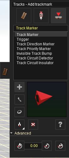
The third mode in the Track Menu is Trackmark Mode. Trackmark mode is used for the management of Trackmarks and Triggers. These are used to assist in setting up the rules for a session, which allows you to design operations for your route. Click LMB on the Trackmark Mode (V) to change the Track Tab menu to the Trackmark Mode menu.
 Add Trackmark
To add a Trackmark, Click LMB on the Add Trackmark (A) button. Click LMB at a point on the track. A trackmark will be placed on the track and will be “attached” to it. So if you move the track it will move with it.
 Move Trackmark
Click LMB on Move Trackmark (M). Then Click LMB+H on a Trackmark Object on your track. Drag your mouse along the track to move the object to a different position.
 Rotate Trackmark
Select Rotate Trackmark (R) and the default direction of the Trackmark is reversed.
 Get Trackmark
Click on the Get Trackmark (G) tool and then Click LMB on a trackmark already placed at the track. That trackmark now appears in the selection window. Change the mode to Add Object (A) and Click LMB again at another point on the track where you wish to place another copy of the trackmark.
 Delte Trackmark
Select Delete Trackmark (D) then Click LMB on a trackmark to delete it.
 Define Name
To name your trackmarks so that you can find them again later on and use them in rules, Click LMB on Define Name (N). Then click on the trackmark and a dialogue box comes up where you can name the trackmark.
Advanced
Advanced Trigger Management Tools The advanced settings of the Trackmark tools menu are used to set the radius of triggers. The radius defines the scope of the trigger and is explained in the previous section.
 Get Radius
Click on the Get Radius tool and then Click LMB on a trigger. The trigger’s radius will now be in the text field adjacent to the button. The triggers have a default radius of 20 meters so this may not appear to have changed.
 Apply Radius
Click on Apply Radius then Click LMB on a trigger to apply the value in the radius field to that trigger.
 Edit Radius
Click on Edit Radius then Click LMB on a trigger and drag the mouse with the LMB still being held down to change the trigger radius. There is no visual indication of the radius as you drag it however. Use Get Radius to find out the new radius of that trigger.
- See Also
Return to TRS19 Help Page


