Help:Objects Tab
| Line 1: | Line 1: | ||
There are | There are | ||
two different types of objects | two different types of objects | ||
| − | - objects and splines. | + | - objects and splines.Open the Objects Menu by |
| + | clicking on the Objects Tab. | ||
| + | (F3) | ||
== Objects == | == Objects == | ||
| − | + | The default mode is Add | |
| − | + | ||
| − | + | ||
Objects. Begin by scrolling | Objects. Begin by scrolling | ||
through the list of objects by | through the list of objects by | ||
Revision as of 12:51, 19 February 2014
There are two different types of objects - objects and splines.Open the Objects Menu by clicking on the Objects Tab. (F3)
Contents |
Objects
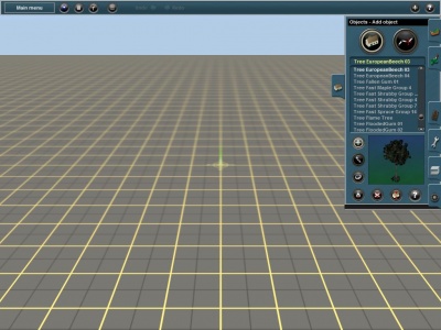
The default mode is Add Objects. Begin by scrolling through the list of objects by clicking on the left and right arrows of the object list. The selected object shows as a rotating 3D object in the viewer window.
 Add Object
Check that you are in Add Object mode, or Click LMB on Add Object (A) to select this mode. Click LMB on the terrain and the selected object is placed wherever you click. You can repeat this several times quickly adding a number of trees or buildings.
 Move Object
Click on the Move Object (M) and Click LMB+H on any object and then drag the object around the terrain to new positions.
 Rotate Object
Now click on the Rotate Object (R) and Click LMB+H and move the mouse left and right to rotate the objects. Note that a display shows you the number of degrees of rotation. You can use the move and rotate tools to create rows of trees or to align houses along a road. You can set objects to “randomly rotate” or not by choosing the Randomly Rotate option in the Surveyor Options menu from the Main Menu. To find a particular object in the list of objects, click on the Object Selection text box, and then type the first few letters of the object name. Type in “tree” and the list automatically positions alphabetically at “tree”. Click on the Up and Down arrows (or use the “+” or “-” keys) to scroll up and down the list. 139
Above the Object Viewer Window are the Object Region and Object Type lists. Scroll through and select either a region or an object type or both in order to shorten the selection list.
 Get Object
Click on the Get Object (G) tool and then Click LMB on an object already placed on the terrain. Notice that the object selected now appears in the selection window. Change the mode to Add Object (A) and Click LMB again on the terrain where you wish to place another copy of the newly selected object.
 Delete Object
Select Delete Object (D) then Click LMB to delete an object. Continue Clicking LMB to delete a number of objects. If you click on the wrong object, click on Undo (Ctrl-Z) to undo the last action and replace the last deleted object.
 Height Adjust
When placed on a route, Objects are placed at ground level at that point in the route. If the ground is raised the object follows it. But you can place an object at a relative height to the ground at any point. Click LMB on Height Adjust (H) to enable the adjustment of 140 the height of any Object. Note that only objects which have been designed to be height adjustable will allow you to adjust their height. So if you cannot adjust the height of an object, the likely reason is that it wasn’t designed to do so. While in the flight of fancy shown below we have height adjusted a station to make it defy gravity, this function is very useful. For example, you can place objects on top of each other such as a building on a platform. Holding the Ctrl key in conjunction with this move will adjust the object’s height in increments of 0.1 units and holding the Shift key will change the height by units of 0.05.
 Edit Properties
Click LMB on Edit Properties (N). Then Click LMB on any object in your route. A menu will then open up allowing you to edit the properties of the object. For simple objects, this usually involves naming the object if you wish. For more complex operating industries, you are given the opportunity to change production and consumption rates for resources and other properties as we experienced in the 141 earlier tutorial with the power plan and the coal plant objects. Finally there is an option to move the object between layers. See section 10 for more details about layers. __________________
Spline
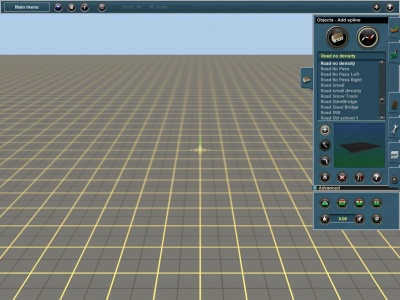
Splines are generally long thin objects such as roads, power lines, fences and rows of trees. They consist of two or more “spline points” denoted by white circles. These spline points can be placed any distance apart and the spline object is then “stretched” between the spline points as you place them on the route. To enter Object Spline mode, Click LMB on the large Spline Mode (S) button at the top left of the tab menu.
 Add Spline
Click LMB on the terrain to anchor the first spline point, and Click LMB again some distance away to place the second spline point. You will see white circles at each end of the spline. These spline points determine the points of a spline that may be selected or moved. To extend the spline further, Click LMB again on the last spline point, then Click LMB once more nearby to extend the spline. Holding down the Ctrl key then placing several spline points is another way. Release the Ctrl Key and place your final spline point to anchor the spline in place
 Move Spline
Select the Move Spline (M) tool and then Click LMB+H and dragging the spline point to a new position. To set the spline poit at a specific location, hold the Shift key when placing it. This shortcut can be used to place spline on top of one another.
 Split Spline
If a spline is already curved, you can split it into two sections by using the Split Spline (Q) tool. Click LMB on the middle spline (or any non-end spline point) to separate them.
 Get Spline
Click LMB on the Get Spline (G) tool and then Click LMB on a spline object already placed on the terrain. The spline object selected now will appear in the selection window. Change the mode to Add Spline (A) and Click LMB again on the terrain where you wish to place the newly selected spline object.
 Delete Spline
Click LMB on Delete Spline (O) then click on a section of spline between two adjacent white circles to remove unwanted spline sections. If you delete a section that is not an end section of a spline, the spline will be split into two splines.
 Toggle Traffic
Many roads will have vehicles travelling on them automatically, this can be seen while in Surveyor after placing the roads. Clicking LMB on Toggle Traffic turns all traffic off on the roads.Clicking LMB on the button again will have traffic resume.When toggling traffic on and off, it affect all spline roads on your route.
 Edit Properties
Click LMB on Edit Properties (N). Then Click LMB on any object in your route. A menu will then open up allowing you to edit the properties of the object.
Advanced
Click LMB on the Advanced Menu (Shift F3) to access even more tools. A drop down menu is then revealed.
 Spline Height
The Spline Height (H) tool can be used to raise or lower the height of certain types of splines (for example catenaries or road bridges). Click LMB on Spline Height then Click LMB+H on a spline point (the white circle) and drag the mouse forward or backwards.
 Delete Spline Point
Click LMB on Delete Spline Point (X) and then Click LMB on a white spline circle to remove unwanted spline points. You cannot delete an end spline point, but you can delete the whole section using the Delete Spline (D) tool.
 Insert Spline Point
Click LMB on Insert Spline Point (I) then Click LMB between two existing spline points. Notice that a new spline point is created.
 Smooth Spline
Smooth Spline (S) levels the track between two spline points, bringing the land up or down to match the levelled spline.
 Get Vertex Height
Click LMB on the Get Vertex Height and Click LMB on the highest spline point on your spline. The height is displayed in the Height Value box.
 Apply Vertex Height
Click LMB on Apply Vertex Height then Click LMB on another spline point. The spline point is raised to the same height as you first vertex.
 Remove Gradient
Click LMB on Remove Gradient and then Click LMB on a spline section to remove the gradient between two spline points.
 Edit Propertires
This can be used to name the spline and also set its layer.

